Transverse reinforcement design

2 Symbols
| Symbol | Unit | Description |
|---|---|---|
| \(V_{Ed}\) | kN | Shear force acting |
| \(V_{Rd,c}\) | kN | Design resistant shear force for an element without shear force reinforcement |
| \(V_{Rd,s}\) | kN | Calculation value of the shear force equilibrated by shear reinforcement in the ultimate limit state |
| \(V_{Rd,max}\) | kN | Calculation value of the maximum shear force an element can withstand before the concrete rods are collapsed. |
3 Calculation efforts
The transverse reinforcement is design at ULS in accordance with Eurocode 2.
3.1 Elements without transverse reinforcement
- Resistant shear force for an element without shear reinforcement:
\[ V_{Rd,c}=max\left\{\begin{array}{l}V_{Rd,c1}=\left[C_{Rd,c}k\sqrt[3]{100\rho_1f_{ck}}+k_1\sigma_{cp}\right]b_wd\\V_{Rd,c2}=\left[v_{min}+k_1\sigma_{cp}\right]b_wd\end{array}\right. \]
With:
\[ C_{Rd,c}=\frac{0.18}{\gamma_c} \]
- Percentage of longitudinal reinforcement : \[ \rho_1=\frac{A_{sl}}{b_wd}\not>2‰ \]
With:
\[ k=min\left\{2;\;1+\sqrt{\frac{0.2\;m}d}\right\} \]
- Compressive stress of the concrete : \[ \sigma_{cp}=\frac{N_{Ed}}{A_c}\leq0.2f_{cd} \]
With:
\[ v_{min}=\frac{0.053}{\gamma_c}k^{3/2}\sqrt{f_{ck}} \]
\[ k_1=0.15 \]
No transverse reinforcement is required if \(V_{Ed}\leq V_{Rd,c}\).
3.2 Maximum shear force
Even if no transverse reinforcement is required, the following condition must be respected : \[ V_{Ed}\leq V_{Rd,max} \] Where \(V_{Rd,max}\) is the design value of the maximum shear force that an element can support before the concrete rods are crushed:
\[ V_{Rd,max}=\alpha_{cw}v_1f_{cd}b_wz\frac1{\tan\theta+co\tan\theta} \] With :
\[ z=0.9d \]
\[ \alpha_{cw}=\left\{\begin{array}{lc}0<\sigma_{cp}<0.25f_{cd}&\alpha_{cw}=1+\frac{\sigma_{cp}}{f_{cd}}\\\begin{array}{l}0.25f_{cd}<\sigma_{cp}<0.5f_{cd}\\0.5f_{cd}<\sigma_{cp}<f_{cd}\end{array}&\begin{array}{l}\alpha_{cw}=1.25\\\alpha_{cw}=2.5\left(1-\frac{\sigma_{cp}}{f_{cd}}\right)\end{array}\end{array}\right. \]
3.3 Tensile force in the longitudinal reinforcement
The tensile force in the longitudinal reinforcement is calculated from the following expression. The force to be taken up by the reinforcements cannot be exceeded. \[ F_{td}=\frac{M_{Ed}}z+\frac12V_{Ed}\left(co\tan\theta-co\tan\alpha\right)\leq\frac{M_{Ed,max}}z \]
4 Calculation of transverse reinforcement
The transverse reinforcement is designed at the ULS in accordance with Eurocode 2.
When \(V_{Ed}>V_{Rd,c}\), the transverse reinforcements are required
It is advised to choose an inclination of the concrete rods between \(1.0\leq co\tan\theta\leq2.5\)
4.1 Checking the compression of concrete connecting rods
It should be checked that the compression force of the concrete rods do not exceed :
\[ V_{Ed}\leq V_{Rd,max}=b_wzv_1f_{cd}\frac{co\tan\theta+co\tan\alpha}{1+\left(co\tan\theta\right)^2} \]
With:
- \(z=0.9d\)
- \(v_1=0.6\left(1-\frac{f_{ck}}{250}\right)\)
4.2 Calculation of shear reinforcement
The force taken up by the transverse reinforcement is calculated as follows:
\[ V_{Rd,s}=\rho_wf_{ywd}\sin^2\alpha\left(co\tan\theta+co\tan\alpha\right)b_wz=\frac{A_{sw}}{sb_w\sin\alpha}f_{ywd}\sin^2\alpha\left(co\tan\theta+co\tan\alpha\right)b_wz \]
The force taken up by the transverse reinforcements must be compared to the design shear force to find the steel section required to take up the design shear force \(V_{Ed}\).
\[ \frac{A_{sw}}s=\frac{V_{Ed}}{zf_{ywd}\left(co\tan\theta+co\tan\alpha\right)\sin\alpha} \]
4.3 Minimum percentage of transverse reinforcement
The percentage of transverse reinforcement is calculated as follows:
\[ \rho_w=\frac{A_{sw}}{sb_w\sin\alpha} \]
Where: * \(A_{sw}\) is the section of transverse reinforcements at a given cross-section * \(s\) is the spacing of the transverse reinforcement * \(b_w\) is the width of the section * \(\alpha\) is the inclination of the transverse reinforcements with respect to the longitudinal reinforcements.
Even when no shear reinforcement is necessary, a minimum transverse reinforcement is required. The percentage of minimum transverse reinforcement is calculated as follows:
\[ \rho_{w,min}=0.08\frac{\sqrt{f_{ck}}}{f_{yk}} \]
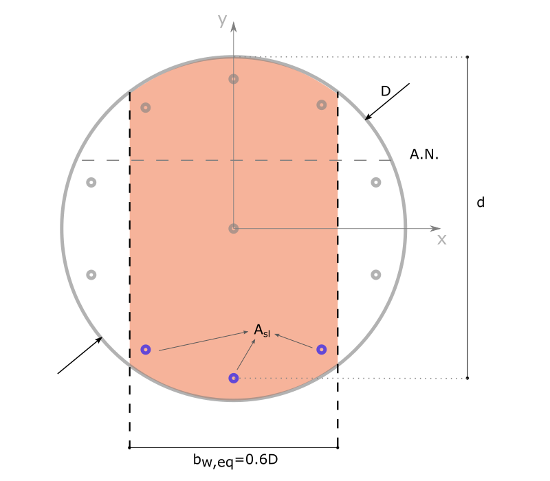
5 Cas particulier des sections circulaires (pieux)
The case of circular sections is not dealt with in Eurocode 2 - Part 1.1. The Application Guide of Eurocode 2 (FD P18-717) makes some proposals which are summarised below when there are at least 6 longitudinal bars, which is usually the case in common situations.
In the context of the verification of the shear force and the calculation of the transverse reinforcement, the circular section is assimilated to an equivalent rectangular section with the following dimensions
Width: \(b_{w,eq}=0.6D\)
Lever arm: \(z=0.9d\)
where D is the diameter of the pile and d is the effective height of the section.
Only the tensile reinforcement within this equivalent section is included in the \(A_{sl}\) term.