ULS analysis

1 Introduction
This document details how the ULS analysis is performed for circular sections and for rectangular reinforced concrete sections.
2 Circular section
This chapter details the calculation of a circular reinforced concrete section subjected to biaxial bending (ULS).
2.1 Notes
2.1.2 Forces
| Symbol | Unit | Description |
|---|---|---|
| \(N\) | MN | Normal force applied to the section |
| \(M_x\) | MNm | Bending moment applied to the section around the positive semi-axis OX |
| \(M_y\) | MNm | Bending moment applied to the section around the positive semi-axis OY |
| \(V_x\) | MN | Shear force applied to the section along the positive semi-axis OX |
| \(V_y\) | MN | Shear force applied to the section along the positive semi-axis OY |
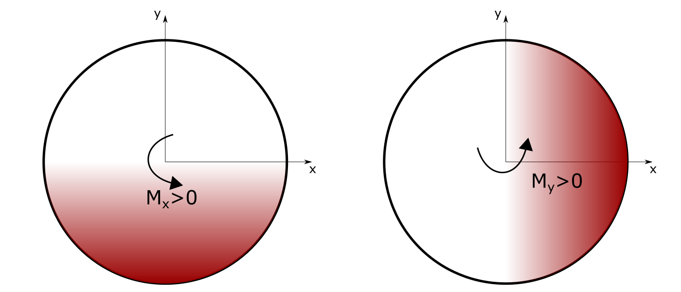
The right hand rule applies:
- A moment \(M_x>0\) compresses the lower fibre of the section (left figure)
- A moment \(M_y>0\) compresses the fibre to the right of the section (right figure)
2.1.3 Stresses
| Symbol | Unit | Description |
|---|---|---|
| \(\sigma_{s,i}\) | MPa | Stress in steel (“i” bar) |
| \(\sigma_c\) | MPa | Compressive stress in concrete |
| \(f_{cd}\) | MPa | Allowable compressive stress of concrete (design value) |
| \(f_{ck}\) | MPa | Allowable compressive stress of concrete (characteristic value) |
| \(f_{yd}\) | MPa | Allowable steel stress (design value) |
| \(f_{yk}\) | MPa | Allowable steel stress (characteristic value) |
2.2 Principle of ULS calculation
The principle of calculation of circular sections (piles) under ULS consists in comparing the resulting torsor applied to the section with the interaction diagram (N, M) of the reinforced concrete section.
This interaction diagram determines the allowable range (inner area of the interaction diagram, including the boundary) in which the torques (N, M) that can be taken up by the reinforced concrete circular section.
2.2.1 Calculation assumptions
The ULS design of reinforced concrete sections takes into account the following assumptions:
- Hypothesis 1: The cross sections remain plane and there is no relative slippage between the reinforcement and the concrete. The deformation diagram is therefore linear.

- Hypothesis 2: The tensile strength of concrete is neglected.

- Hypothesis 3: The strain diagram of the section corresponds to a limit state if it passes through one of the pivots A, B, C. These pivots are defined hereafter.
The constitutive laws of concrete and steel are provided in the Materials chapter of this manual.
The design strain levels (\(\varepsilon\)) of each material, in particular concrete (\(\varepsilon_c\)) and steel (\(\varepsilon_s\)), are defined by the user and therefore fixed before the interaction diagrams are established.
2.2.2 Generation of the interaction diagram
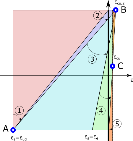
The principle of generating interaction diagrams is based on the analysis of all possible bending modes of the section. In order to optimise the work of the section, this scan is done based on the usual pivots A, B and C. The range of possible regions are described as follows:
- Region 1 (pivot A): it consists in keeping the strain of the lower steels at the maximum value \(\varepsilon_{ud}\) while varying the strain of the upper concrete fibre between the value of the limit strain of the steel and a zero strain. The section remains completely taut in this region and the contribution of the concrete is therefore neglected. The resisting force is only provided by the steel section. The left limit of the region corresponds to a simple tensile condition.
- Region 2 (pivot A): keeping the strain in the lower steels fixed at \(\varepsilon_{ud}\), the strain in the upper fibre of the concrete increases from its zero value to \(\varepsilon_{cu,2}\). The section starts to be compressed and the neutral axis starts to move towards the centre of the section. The curvature of the section becomes maximum for the diagram passing through \(\varepsilon_s=\varepsilon_{ud}\) and \(\varepsilon_c=\varepsilon_{cu,2}\). The section is partially compressed at the top.
- Region 3 (pivot B): by setting the upper strain value to \(\varepsilon_{cu,2}\), the strain of the lower steels starts to decrease progressively until the elastic limit \(\varepsilon_s=\varepsilon_{s}=f_{yd}/E_s\). The neutral axis continues to descend towards the centre of the section, causing the compressed height to increase and the curvature to decrease. The section is partially compressed at the top.
- Region 4 (pivot B): the strain of the upper concrete fibre remains fixed at \({cu,2}\), the strain of the lower steels continues to decrease, even entering a compressive working mode, until the strain of the lower concrete fibre is cancelled. The neutral axis reaches the lower level of the section and the curvature continues to decrease. The section becomes compressed with little eccentricity.
- Region 5 (pivot C): in this region, the strain diagram rotates around the pivot C located at the level of the fibre that follows a strain \(\varepsilon_c=\varepsilon_{cu}\) at the end of the previous region, until reaching a uniform strain equal to \(\varepsilon_c=\varepsilon_{cu}\) in the upper and lower fibre of the concrete. The section is fully compressed, the last state corresponding to simple compression.
2.2.3 Calculation of the resisting forces
The resistant force of the section is calculated for each strain diagram. It is composed of a part coming from the steel and another part coming from the concrete (only if it is compressed, the tensile contribution is neglected).
2.2.3.1 Resistance force of concrete
The force of the concrete is calculated on the basis of the parabola-rectangle law. \[ \left\{\begin{array}{lc}\sigma_c=\left(\varepsilon_c-0.25\varepsilon_c^2\right)f_c&0<\varepsilon_c<2‰\\\sigma_c=f_c&2‰\leq\varepsilon_c\leq3.5‰\end{array}\right. \]
Resistant forces on the “rectangle” part:
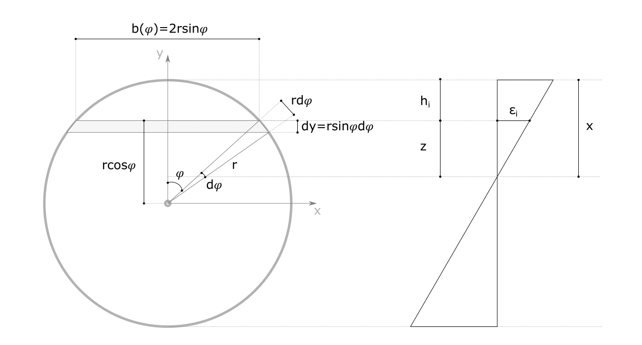
Resistant normal force: \[ N_{c1}=\int_0^xf_cb\left(\varphi\right)\operatorname dy \]
Resistant moment: \[ M_{c1}=\int_0^xf_cb\left(\varphi\right)r\cos\varphi\operatorname dy \]
Resistant forces on the “parabola” part
Resistant normal force: \[ N_{c2}=\int_0^x\sigma_{ci}\left(\varphi\right)b\left(\varphi\right)\operatorname dy \]
Resistant moment:
\[ M_{c2}=\int_{x_2}^{x_3}\sigma_{ci}\left(\varphi\right)b\left(\varphi\right)r\cos\left(\varphi\right)\operatorname dy \]
2.2.3.2 Resistance effort of the steel
The force provided by the steel is accounted for on the basis of the bilinear law. \[ \left\{\begin{array}{lc}\sigma_s=E_s\varepsilon_s&0<\varepsilon_s<\varepsilon_y\\\sigma_c=\sigma_y&\varepsilon_y<\varepsilon_s\leq\varepsilon_{ud} \end{array}\right. \]
2.2.3.2.1 Discrete distribution of steel bars
- For each bar of section \(A_i\) :
- Stress in bar “i” from the strain diagram:
\[ \sigma_i=\sigma(\varepsilon_i) \]
- Force mobilised in the “i” bar:
\[ F_i=\sigma_i\cdot A_i \]
- Resulting force on all steel bars :
\[ N_s=\sum_iF_i \]
2.2.3.2.2 Continuous and homogeneous distribution of the steel section

- Rectangular stress diagram (plastic zone) between \(\varphi_1\) and \(\varphi_2\) :
\[ N_{s,rectangular}=2\int_{\varphi_1}^{\varphi_2}f_y\overline{a_s}r_s\operatorname d\varphi \]
\[ M_{s,rectangular}=2\int_{\varphi_1}^{\varphi_2}f_y\overline{a_s}r_sr_s\cos\varphi\operatorname d\varphi \]
- Triangular stress diagram (elastic zone) between \(\varphi_2\) and \(\varphi_3\) :
\[ N_{s,triangular}=2\int_{\varphi_2}^{\varphi_3}\sigma_{s,i}\left(\varphi\right)\overline{a_s}r_s\operatorname d\varphi \]
\[ M_{s,triangular}=2\int_{\varphi_2}^{\varphi_3}\sigma_{s,i}\left(\varphi\right)\overline{a_s}r_sr_s\cos(\varphi)\operatorname d\varphi \]
- Rectangular stress diagram (plastic zone) between \(\varphi_3\) and \(\varphi_4\): formulation identical to the first case between \(\varphi_1\) and \(\varphi_2\).
3 Rectangular section
3.1 Notes
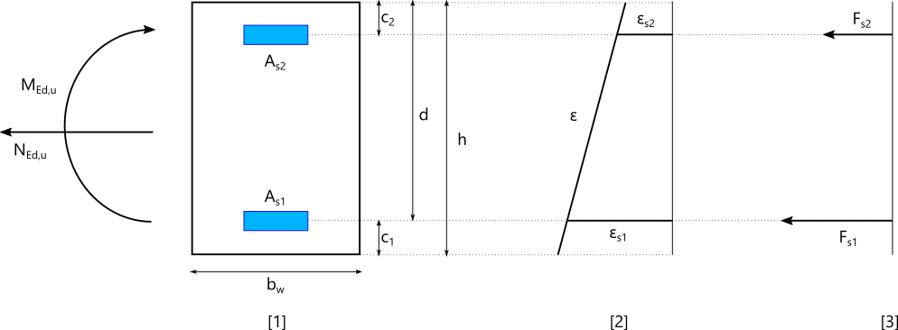
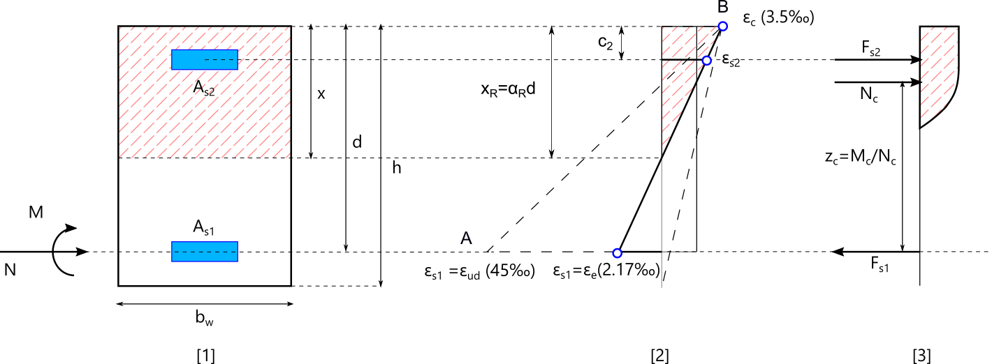
3.1.1 Geometry
| Symbol | Unit | Description |
|---|---|---|
| b | m | Width of the section |
| h | m | Total height of the section |
| d | m | Effective section height |
| \(c_1\) | m | Distance between the top of the section and the centre of gravity of the tension steels |
| \(c_2\) | m | Distance between the bottom of the section and the centre of gravity of compressed steels |
| x | m | Position of the neutral axis from the most compressed fibre |
| \(A_{s1}\) | m² | Tension steel section |
| \(A_{s2}\) | m² | Compressed steel section |
| \(z_R\) | m | Lever arm associated with \(M_R\) |
3.1.2 Forces
| Symbol | Unit | Description |
|---|---|---|
| \(N\) | MN | Normal force applied to the reinforced concrete section |
| \(M\) | MNm | Bending moment applied to the reinforced concrete section (at the bottom reinforcement) |
| \(M_c\) | MNm | Bending moment taken up by concrete alone |
| \(N_c\) | MN | Normal force taken up by the concrete alone |
| \(F_{s1}\) | MN | Force taken up by the tensioned reinforcement |
| \(F_{s2}\) | MN | Force taken up by the compressed reinforcement |
| \(M_R\) | MNm | Limit moment of the reinforced concrete section beyond which a compressed reinforcement must be provided in order to ensure an optimised behaviour of tension reinforcement |
| \(N_R\) | MN | Normal force taken up by the concrete associated with \(M_R\) |
3.1.3 Stresses
| Symbol | Unit | Description |
|---|---|---|
| \(\sigma_{s1}\) | MN/m² | Stress in tension steels |
| \(\sigma_{s2}\) | MN/m² | Stress in compressed steels |
| \(\sigma_c\) | MN/m² | Compression stress of concrete |
| \(f_{cd}\) | MN/m² | Allowable compression stress of concrete (design value) |
| \(f_{ck}\) | MN/m² | Allowable compression stress of concrete (characteristic value) |
| \(f_{yd}\) | MN/m² | Allowable stress of steel (design value) |
| \(f_{yk}\) | MN/m² | Allowable stress of the steel (characteristic value) |
3.2 Principle of ULS calculation
The design of reinforced concrete section at the ULS is performed using a strain based analysis.
3.2.1 Calculation assumptions
The ULS design of reinforced concrete sections takes into account the following assumptions:
- Hypothesis 1: The cross sections remain plane and there is no relative slippage between the reinforcement and the concrete. The deformation diagram is therefore linear.
- Hypothesis 2: The tensile strength of concrete is neglected.
- Hypothesis 3: The strain diagram of the section corresponds to a limit state if it passes through one of the pivots A, B, C. These pivots are defined hereafter.
The constitutive laws of concrete and steel are provided in the Materials chapter of this manual.
3.2.2 Behaviour modes of the section
The optimised design of a reinforced concrete section requires a strain diagram that contains a limit strain, either in concrete or steel. These limit strains are characterised by pivots
Three pivots are used to define the behaviour mode of the section:
- Pivot A: the strain of tension steels corresponds to its maximum permissible value (\(\varepsilon_{ud}\))
- Pivot B: the strain of the most compressed concrete fibre corresponds to the maximum permissible strain of the concrete (\(\varepsilon_{cu}\))
- Pivot C: the strain of the concrete is considered to be equal to the maximum permissible elastic strain (\(\varepsilon_{ce}\)) on the compressed height of the concrete.
\(x\) is the position of the neutral axis from the most compressed fibre.
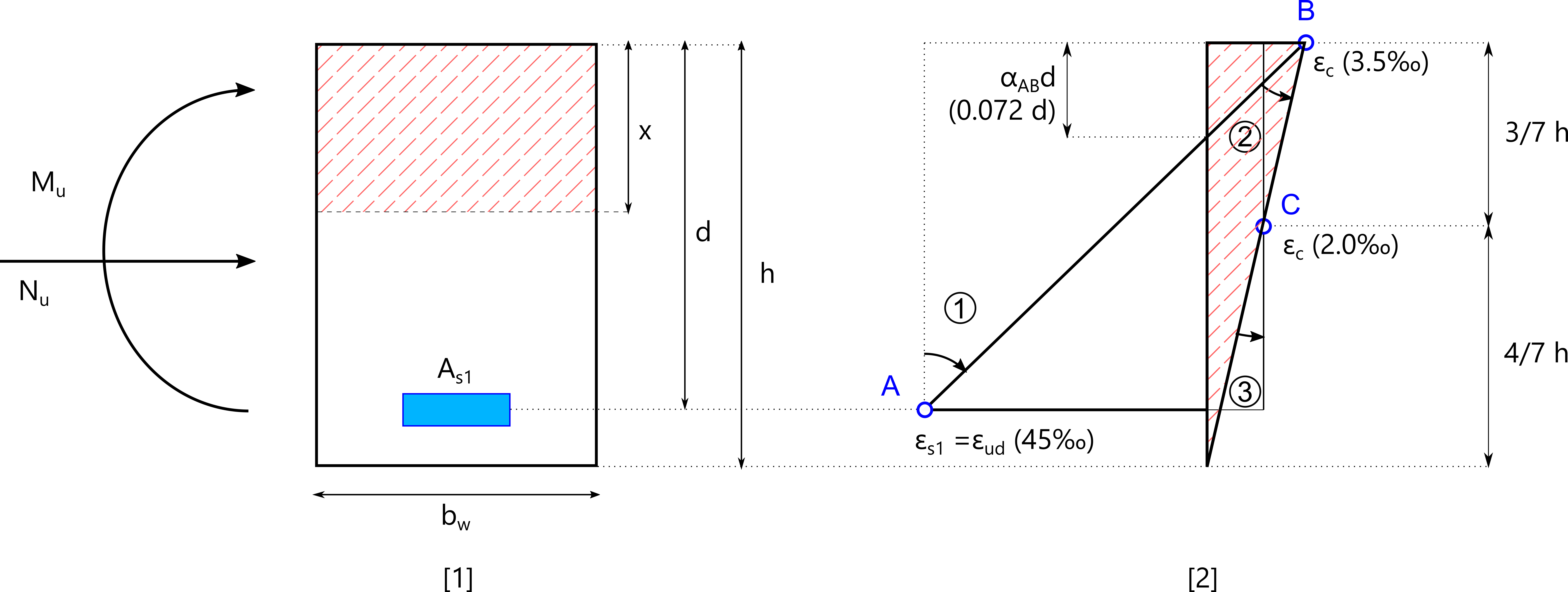
If the strain diagram passes through both pivots A and B, then: \[ x=\frac{\varepsilon_{cu}}{\varepsilon_{cu}+\varepsilon_{ud}}d=\frac{3.5‰}{3.5‰+45‰}d=0.072d \] The strain diagrams of the section can be found in one of the three domains defined by the pivots:
- Domain 1 : \(0<x<0.072d\) → Partially compressed section
- Domain 2 : \(0.072d\leq x<h\) → Partially compressed section
- Domain 3 : \(h\leq x\) → Fully compressed section
3.2.2.1 Partially compressed section
Depending on the position of the neutral axis, 2 cases are possible:
- \(0.072d\leq x<h\)
The strain diagram of the section is in domain 2
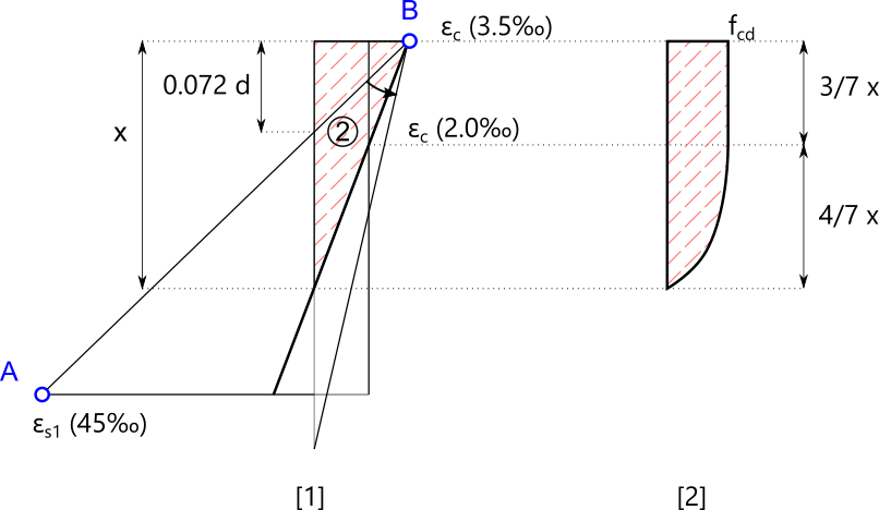
The shortening of the most compressed fibre is \(\varepsilon_c=3.5‰\), which corresponds to a stress equal to \(f_{cd}\).
The stress diagram has two parts: a straight part over a height of \(3/7x\) and a parabolic part over a height of \(4/7x\).
This distribution of heights is due to the layout of the concrete constitutive law. The strain diagram is linear over the compressed height:
- Concrete strain greater than 2‰ generate a stress equal to \(f_{cd}\).
- Concrete strain below 2‰ follow a parabolic stress distribution ranging from 0 and \(f_{cd}\).
2‰ corresponds to the maximum strain of the elastic domain, i. e. \(2‰/3.5‰=4/7\) of the compressed height.
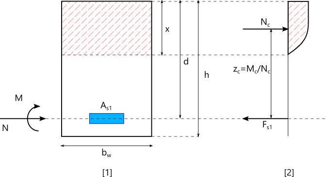
Normal force and moment taken up by the concrete: \[ N_c=0.81bxf_{cd} \label{Nc} \]
\[ M_c=0.81bxf_{cd}(h-0.416x) \label{Mc} \]
The relationship between \(M_c\) and \(N_c\) can be deduced from the previous expressions: \[ M_c=N_c(h-0.514\frac{N_c}{bf_{cd}}) \label{McNcRelation} \]
- \(0<x<0.072d\)
The strain diagram of the section is in domain 1.
The shortening of the most compressed fibre is less than 3.5 ‰ and the diagram can have one of the two layouts shown below.

In this case: :
For a value of x between 0 and 0.072d, the value of the force lever arm \(z=M_c/N_c\) is between:
\(z=d\) for \(x=0\)
\(z=0.97d\) for \(x=0.072d\)
Since the concrete section is overabundant, it is not necessary to add a compressed reinforcement.
We find that the relative variation of the lever arm is very small and that it is not necessary to evaluate x with great precision, which allows the use of the Nc and Mc equations an its relation as in domain 2.
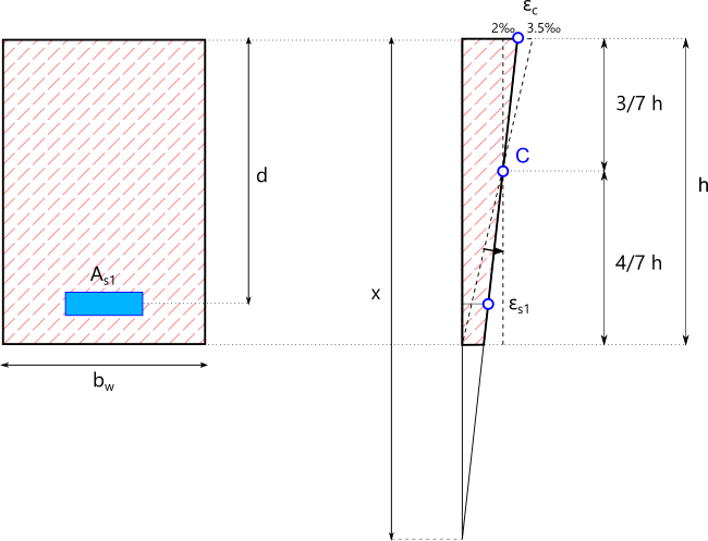
3.2.2.2 Fully compressed section
The strain diagram of the section is in domain 3 and passes through pivot C.
The stress diagram is composed of a straight part over a total height equal to \(3/7h\) and a parabolic part over a total height equal to \(4/7h\).
The equilibrium state of the section is obtained from the balance of forces and moments, allowing the deformation diagram associated with the applied torsor to be obtained.
3.3 Calculation of the required reinforcement sections
The formulation described below consists of the proposition of the most economical solution. In principle, we avoid to propose a reinforcement whose relative strain is smaller than the elastic strain \(\varepsilon_e\). If this is not possible, the force in the reinforcement will be minimised.
3.3.1 Partially compressed section
A section is partially compressed if the forces N and M counterbalanced by the section and calculated at the lower reinforcement verify the following equation: \[ \left(d-c_2\right)N-M<\left(0.337-0.81\frac{c_2}h\right)bh^2f_{cd} \]
- \(M\leq M_R\)
In this case, no compression reinforcement is required.
The moment is counterbalanced by the concrete alone. The lower reinforcement elongation is greater than \(\varepsilon_e\), this reinforcement is thus efficiently used.
The equilibrium calculation allows to find the necessary steel section in the lower part.
- \(M_R< M\)
In this case, a compressed reinforcement should be added to ensure that the tension reinforcement is used properly and that the concrete stress does not exceed the permissible stress.
The equilibrium calculation leads to the necessary steel sections on each side to ensure that the acting forces are correctly taken up.
3.3.2 Fully compressed section
A section is fully compressed if the forces N and M (calculated at the level of the lower reinforcement) result in a purely compressive deformation diagram (no tensile zone). In this case, the deformation diagram passes through point C.
If there are two reinforcements in the section, the lower reinforcement is the less well used of the two since it has the lowest relative shortening. Therefore, a balance of forces should be considered without establishing a bottom reinforcement.
The equilibrium calculation leads to the steel sections necessary to ensure that the acting forces are correctly taken up by the steel and concrete.
3.3.3 Tension only section
The tensile strength of concrete is neglected. Only the reinforcement forces counterbalance the forces applied to the section. The most economical solution is to guarantee that the centre of gravity of the reinforcement is at the point of application of the normal force.
Let’s note:
- \(e_{s1}\) distance between the point of application of normal force and the tension reinforcement
- \(e_{s2}\) distance between the point of application of normal force and the compressed reinforcement
The steel sections are obtained from moment equilibrium: \[ A_{s2}=\frac{Ne_{s1}}{\left(e_{s1}+e_{s2}\right)\sigma_{s2}} \]
\[ A_{s1}=\frac{Ne_{s2}}{\left(e_{s1}+e_{s2}\right)\sigma_{s1}} \]
The stresses in steel are considered equal to \(\sigma=\sigma(\varepsilon_{ud})\).