SLS analysis

1 Introduction
This document details how the SLS analysis is performed for circular sections and for rectangular reinforced concrete sections.
2 Circular section
This chapter details the calculation of a circular reinforced concrete section subjected to biaxial bending (SLS).
2.1 Notes
2.1.2 Efforts
| Symbol | Unit | Description |
|---|---|---|
| \(N\) | MN | Normal force applied to the centre of gravity of the section |
| \(M\) | MNm | Bending moment applied to the centre of gravity of the section |
2.1.3 Stresses
| Symbol | Unit | Description |
|---|---|---|
| \(\sigma_{s}\) | MPa | Stress in steels |
| \(\sigma_c\) | MPa | Compressive stress in concrete |
| \(f_{ck}\) | MPa | Allowable compressive stress of concrete (characteristic value) |
| \(f_{yd}\) | MPa | Allowable steel stress (design value) |
| \(f_{yk}\) | MPa | Allowable steel stress (characteristic value) |
2.2 SLS check principle
The SLS check is performed using a stress based analysis.
This stress based analysis requires a calculation on an homogenized cross section considering the different deformation moduli of steel and concrete.
2.2.1 Calculation assumptions
The SLS check of reinforced concrete sections takes into account the following hypotheses:
- Hypothesis 1 : The tensile strength of concrete is neglected.
- Hypothesis 2 : The compressive strength of concrete is limited to the permissible stres \(\overline{\sigma_c}\) at SLS.
- Hypothesis 3 : The tensile strength of steel is limited to the permissible stres \(\overline{\sigma_s}\) at SLS.
The constitutive laws of concrete and steel are provided in the Materials chapter of this manuals.
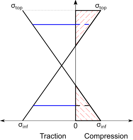
2.2.2 Verification of the reinforced concrete section under SLS
The verification of the SLS reinforced concrete section is performed by homogenising the section in order to take into account the presence of two materials of different stiffnesses. The equilibrium of the section is based on the equilibrium of forces and moments, which allows to find the stress diagram of the section.
In the case of a fully tensioned section, the concrete does not provide any tensile strength. Only the reinforcement forces balance the external forces.
2.2.3 Generation of the interaction diagram
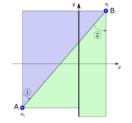
The principle of interaction diagram generation is based on the analysis of all possible bending modes of the section. In order to optimize the work of the section, this scan is done based on the limit stresses of the steel (pivot A) and the concrete (pivot B) at SLS. The stress diagram is homogenized to take into account the different strain moduli of the steel and concrete.
- Region 1 (pivot A): this consists of keeping the homogenized stress of the lower steels equal to the limit working stress at SLS while varying the stress of the upper fiber of the concrete between the working stress of the steel and the allowable stress of the concrete in compression at SLS. The tensile strength of the concrete is neglected. The neutral axis moves towards the center as it goes along. The section changes from pure tension to fully tensioned and then partially compressed at the top of the section.
- Region 2 (Pivot B): In this region the stress in the upper concrete fiber is equal to the allowable stress of the concrete at the SLS while decreasing the stress in the lower steels. The neutral axis continues to descend towards the lower part of the section. The section is fully compressed as soon as the neutral axis exits the lower part of the section.
2.2.4 Calculation of the resisting forces
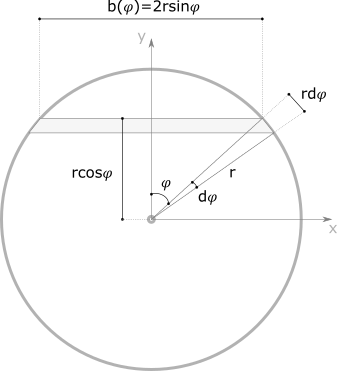
Each homogenized stress diagram is described by the following equation: \[ \sigma_c(y)=ay+b \]
\[ \sigma_c(\varphi)=aRcos\varphi+b \]
Where a is the slope and b is the ordinate at the origin.
2.2.4.1 Resistance force of concrete
- Resistant normal effort:
\[ N_c=\int_0^x\sigma_c(\varphi)b(\varphi)\operatorname dy \]
- Resistant moment:
\[ M_c=\int_0^x\sigma_c(\varphi)b(\varphi)y\operatorname dy \]
2.2.4.2 Resistance force of steel
2.2.4.2.1 Discrete distribution of steel bars
For each bar of section Ai :
Stress in bar “i” from the stress diagram of the homogenized section:
\[ \sigma_i=n \cdot \sigma_{homogénéisée} \]
Where n is the equivalence coefficient: \(n = E_s / E_c\).
- Force mobilized in the “i” bar:
\[ F_i=\sigma_i\cdot A_i \]
Resulting force on all steel bars : \[ N_s=\sum_iF_i \]
2.2.4.2.2 Continuous and homogeneous distribution of the steel section
- Rectangular stress diagram (plastic bearing):
\[ N_{s,rectangular}=2\int_{\varphi_1}^{\varphi_2}f_y\overline{a_s}r_s\operatorname d\varphi \]
\[ M_{s,rectangular}=2\int_{\varphi_1}^{\varphi_2}f_y\overline{a_s}r_sr_s\cos\varphi\operatorname d\varphi \]
- Triangular stress diagram (elastic bearing):
\[ N_{s,triangular}=2\int_{\varphi_2}^{\varphi_3}\sigma_{s,i}\left(\varphi\right)\overline{a_s}r_s\operatorname d\varphi \]
\[ M_{s,triangular}=2\int_{\varphi_2}^{\varphi_3}\sigma_{s,i}\left(\varphi\right)\overline{a_s}r_sr_s\cos(\varphi)\operatorname d\varphi \]
2.2.5 Calculation of the mobilisation rate of the bending strength
The mobilisation rate of the bending resistance is the ratio between the resistant moment and the applied one for the same normal force. It is deduced from the strain diagram calculated for the section under examination.
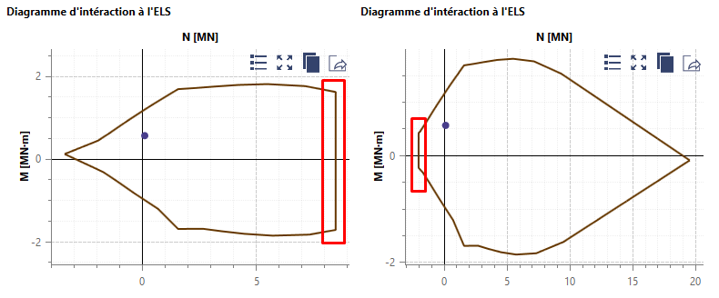
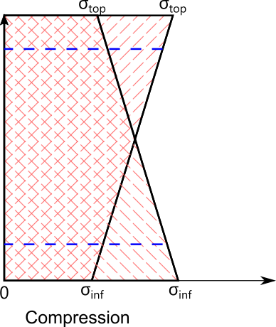
2.2.6 Limit stresses at SLS required by standard NF P 94-262
Scage allows to respect the two limit stresses required by the NF P 94-262 standard:
Average compressive stress of concrete at SLS Characteristic = \(0.3k_3f_{ck}*\) (left figure)
Average tensile stress at SLS Quasi-Permanent = \(600w_k\) (for fully tensioned elements) (right figure)
3 Rectangular section
3.1 Symbols
3.1.1 Geometry
| Symbol | Unit | Description |
|---|---|---|
| b | m | Width of the section |
| h | m | Total height of the section |
| \(A_{s1}\) | m² | Lower steel section |
| \(A_{s2}\) | m² | Upper steel section |
| \(c_1\) | m | Distance between the top of the section and the center of gravity of the lower steels |
| \(c_2\) | m | Distance between the bottom of the section and the center of gravity of the upper steels |
| \(d_2\) | m | Position of the reinforcements \(A_{s2}\) in relation to the lower fiber of the section |
| \(v’\) | m | Position of G’ with respect to the lower fiber of the section |
| G | - | Center of gravity of the rectangular section |
| G’ | - | Center of gravity of the homogenized section |
3.1.2 Forces
| Symbol | Unit | Description |
|---|---|---|
| \(N_s\) | MN | Normal force applied to G |
| \(M_s\) | MNm | Bending moment applied to G |
| \(M\) | MNm | Equivalent bending moment applied to the lower fibre of the section |
| \(N\) | MN | Equivalent normal force applied to the lower fibre of the section |
| \(M'\) | MNm | Equivalent bending moment applied to G’’ |
| \(N'\) | MN | Equivalent normal force applied to G’’ |
| \(F_{s1}\) | MN | Equivalent normal force applied to G’’ |
| \(F_{s2}\) | MN | Force taken up by the compressed reinforcement |
3.1.3 Contraintes
| Symbol | Unit | Description |
|---|---|---|
| \(\sigma_{s1}\) | MN/m² | Stress in tensioned steels |
| \(\sigma_{s2}\) | MN/m² | Stress in compressed steels |
| \(\sigma_c\) | MN/m² | Compressive stress of concrete |
| \(f_{ck}\) | MN/m² | Compressive stress of concrete (characteristic value) |
| \(f_{yd}\) | MN/m² | Allowable compression/tension stress of steel (design value) |
| \(f_{yk}\) | MN/m² | Stress of the steel (characteristic value) |
3.2 SLS check principle
The SLS check is performed using a stress based analysis.
This stress based analysis requires a calculation on an homogenized cross section considering the different deformation moduli of steel and concrete.
3.2.1 Calculation assumptions
The SLS check of reinforced concrete sections takes into account the following hypotheses:
Hypothesis 1 : The tensile strength of concrete is neglected.
Hypothesis 2 : The compressive strength of concrete is limited to the permissible stres \(\overline{\sigma_c}\) at SLS.
Hypothesis 3 : The tensile strength of steel is limited to the permissible stres \(\overline{\sigma_s}\) at SLS.
The constitutive laws of concrete and steel are provided in the Materials chapter of this manuals.
3.2.2 Modes of behavior of the section
Based on the stress diagram generated by the external load (\(M_s\), \(N_s\)), the reinforced concrete section can be in:
- Simple compression: normal compression force and no moment.

- Partially compressed: normal compression force with moment
- Fully compressed: normal compression force with moment.
- Fully tensioned: normal tensile force with moment

3.3 SLS reinforced concrete section check
The verification of the reinforced concrete section with SLS is performed by homogenizing the section in order to take into account the presence of two materials with different stiffnesses. The equilibrium of the section is based on the equilibrium of forces and moments, which makes it possible to obtain the stress diagram of the section.
In the case of a fully tensioned section, concrete does not provide any tensile strength. Only the reinforcement forces balance the external forces.
3.4 Calculation of reinforcement section
3.4.1 Partially and fully compressed
The principle of dimensioning in SLS consists in looking for the minimum cross section verifying the equilibrium of the cross section while guaranteeing that the limit stresses of each material are not exceeded.
3.4.2 Simple traction
In simple traction, the tensile strength of concrete is neglected. Only the reinforcement forces counterbalance the forces applied to the section. The most economical solution is to guarantee that the center of gravity of the reinforcement is at the point of application of normal force.
Let’s note:
- \(e_{s1}\) distance between the point of application of the normal force and the tensioned reinforcement
- \(e_{s2}\) distance between the point of application of the normal force and the compressed reinforcement
The steel sections are obtained from the moments equilibrium: \[ A_{s2}=\frac{Ne_{s1}}{\left(e_{s1}+e_{s2}\right)\sigma_{s2}} \]
\[ A_{s1}=\frac{Ne_{s2}}{\left(e_{s1}+e_{s2}\right)\sigma_{s1}} \]
The stresses in steels are considered equal to the allowable stress in the SLS.
4 Crack opening (\(w_k\))
\[ w_k=s_{r,max}\left(\varepsilon_{sm}-\varepsilon_{cm}\right) \]
| Symbol | Unit | Description |
|---|---|---|
| \(w_k\) | mm | Opening cracks |
| \(s_{r,max}\) | mm | Maximum crack spacing |
| \(\varepsilon_{sm}\) | - | Average reinforcement elongation, under the combination of actions considered, taking into account the contribution of tensioned concrete |
| \(\varepsilon_{cm}\) | - | Average concrete elongation between cracks |
\[ s_{r,max}=k_3c+0.425k_1k_2\frac{\phi_{eq}}{\rho_{p,eff}} \]
| Symbol | Unit | Description |
|---|---|---|
| c | mm | Coating of longitudinal reinforcement |
| \(k_1\) | - | Coefficient function of the adhesion properties of the bars (0.8 for HA bars) |
| \(k_2\) | - | Coefficient taking into account a distribution of longitudinal bars \(k_2 = 0.5\) in bending \(k_2 = 1\) in tension \(k_2=\frac{\varepsilon_1+\varepsilon_2}{2\varepsilon_1}\) in eccentric tension With \(\varepsilon_1\) the largest and \(\varepsilon_2\) the lowest of the relative elongations of the relative elongations of the fibers and the cross-section considered, evaluated on the basis of a cracked cross-section. |
| \(k_3\) | - | Coefficient of coating adjustment, equal to 3.4 |
| \(\phi_{eq}\) | mm | Equivalent diameter of the bars |
| \(\rho_{p,eff}\) | - | Ratio between the steel section and the effective concrete section (\(A_s/A_{c,eff}\)) |
| \(A_{c,eff}\) | m² | Concrete area surrounding the reinforcement stretched over a height \(h_{c,ef}=min\left\{2.5\left(h-d\right)\;;\;\left(h-x\right)/3\;;\;h/2\right\}\) |
\[ \varepsilon_{sm}-\varepsilon_{cm}=max\left\{0.6\frac{\sigma_s}{E_s};\frac{\sigma_s+k_t{\displaystyle\frac{f_{ct,eff}}{\rho_{p,eff}}}\left(1+\alpha_e\rho_{p,eff}\right)}{E_s}\right\} \]
| Symbol | Unit | Description |
|---|---|---|
| \(\sigma_s\) | MN/m² | SLS stress on tensioned reinforcement, calculated by assuming the cracked section |
| \(E_s\) | MN/m² | Elastic modulus of steel |
| \(f_{ct,eff}\) | MN/m² | Average value of the tensile strength of the concrete effective at the time the cracks are expected to occur (\(f_{ct,eff}=f_{ctm}\)) |
| \(k_t\) | - | Coefficient taking into account the loading time \(k_t=0.6\) for short term loading \(k_t=0.4\) for long term loading |