Pile preliminary design module

1 Introduction
As a complement to the detailed structural verification of piles, Scage offers a pile preliminary design module which can be used to quickly obtain the minimum diameter and steel ratio required to achieve internal structural equilibrium for a set of piles subjected to an infinite number of torsors.
This module is complemented by a generator of interaction diagrams that can be used to check the suitability of a reinforcement ratio for a given diameter for isolated torsors.
The aim of this part of the manual is to provide all the information required for its practical use.
2 Materials
Both operating modes share a Materials tab which allows to define the type of concrete and steel as well as the partial coefficients to be taken into account in the calculation.
Please refer to the relevant section of the manual for more details.
3 Pile preliminary simplified design module
This tab allows you to quickly obtain the minimum diameter and steel ratio required to respect the internal structural equilibrium for a set of piles subjected to an infinite number of torsors.
The calculation consists of generating the interaction diagrams for a pile (circular section) for a given diameter and steel ratio. The search is based on a user-defined range of diameters and steel ratios. Each combination and each situation gives rise to a different interaction diagram. Each diagram is then compared with the point scatter plot representing the torsors applied to each pile.
The result is a set of interaction diagrams for the chosen solution, compared with the torsors applied to each pile for each of the combinations and situations considered.
3.1 Search parameters
The search parameters to be defined are as follows:
- List of diameters to be examined: set of diameters to be evaluated, the user can add as many as desired or restrict the value to the diameters imposed by the project or site.
- Longitudinal steel ratios: range of steel ratios to be evaluated. They can be defined in accordance with standard NF P 94-262 or imposed (custom value). The range of values to be examined is defined on the basis of a minimum value and a maximum value.
- Transversal steel ratio: minimum value to be considered, it can be defined in accordance with standard NF P 94-262 or introduced as an imposed value (custom value).
- Position of the centre of gravity of the steel in relation to the edge of the concrete section: this is the distance between the centre of gravity of the steel and the edge of the concrete section. This will have an effect on the tension arm of the tensioned steel and therefore on its contribution to the internal equilibrium of the section.
- Steel stress at SLS: this is the working stress of the steel to be considered at SLS.
3.2 Torsors to be evaluated per pile
The torsors applied to each pile should be defined in the form of a table with several columns:
- Pile to which the torsor applies: each pile is identified by its name.
- Combination: this is the limit state associated with the torsor (ULS or SLS).
- Situation:
- If the combination is ULS : Fundamental or Accidental
- If the combination is at SLS: Characteristic or Quasi-permanent
- Torsor defined with 5 components:
- N: normal force [kN]
- Mx: moment applied around the positive semi-axis OX [kNm]
- My: moment applied around the positive semi-axis OY [kNm]
- Vx: horizontal force applied along the positive semi-axis OX [kN]
- Vy: horizontal force applied along the positive semi-axis OY [kN]
It is entirely possible to import the torsor table from an Excel spreadsheet. To do this, use the Import (Excel) import wizard, which has its own instructions accessible via the help button.
The Delete all button is used to empty the table.
The Sort Torsors button is used to sort the torsors by pile (in ascending alphabetical order).
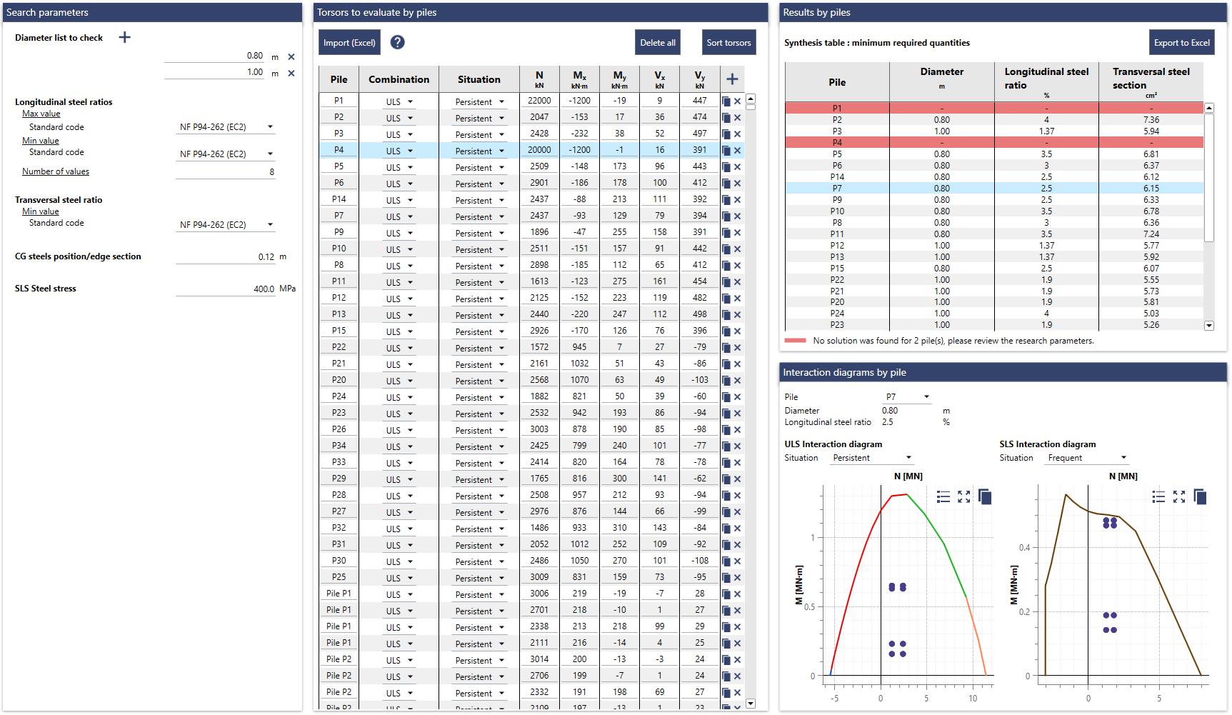
3.3 Results by pile
Once the search parameters and torsors are defined, the calculation can be launched using the Σ button.
The results obtained after the calculation are presented in the form of a table with several columns:
Pile
Diameter chosen to take all the torsors applied to the pile with a reinforcement ratio compatible with the search parameters
Longitudinal steel section: this is the minimum value required. It is presented both as a steel section and as a ratio that it represents in relation to the concrete section.
Transversal steel section: this is the minimum value required.
By construction, the diameter and longitudinal steel ratio are within the range of values defined by the user.
It is possible that the search parameters do not allow the torsors to be included in one or more piles. In this case, the line in the table corresponding to this/these pile(s) is colored red. In this case, the search parameters need to be modified or the load lowering applied to the pile needs to be reviewed.
This results table can be exported using the Export to Excel button (csv format).
This summary table is complemented by a set of interaction diagrams to justify the chosen solution by comparing it with the torsors applied to the pile (N-M point cloud). A total of 4 interaction diagrams can be generated, each associated with a different situation (Fundamental ULS, Accidental ULS, Characteristic SLS and Quasi-permanent SLS).
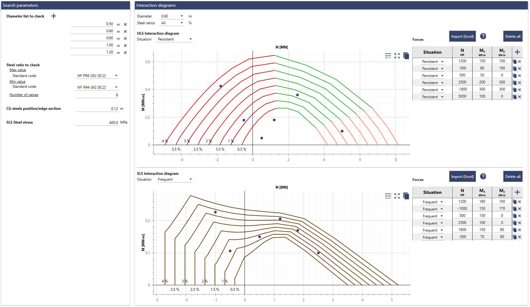
4 Interaction diagram generator
This tab is used to generate a range of interaction diagrams based on a range of pile diameter values to be examined and a range of longitudinal steel ratios.
This tool can be used to validate the choice of diameter and steel ratio to support one or more torsors for each combination/situation considered.
4.1 Search parameters
The search parameters remain identical to those presented in the preliminary pile design module. For more details, please consult this chapter.
4.2 Results
The results consist of a range of interaction diagrams for each diameter-steel ratio pair. They are presented in the form of an N-M curve, which delimits the allowable range (inner zone of the curve), the inadmissible range being outside the curve.
A table to the right of each graph allows a set of torsors (N, Mx, My) to be represented as points on the graph to assess the suitability of the diameter and steel ratio chosen. The torsors are associated with a situation, so they can be compared with the associated interaction diagram.
It is entirely possible to import a table from Excel using the Import (Excel) button, the format to be respected is detailed in the associated manual accessible via the help button next to the button.
The Delete button is used to empty the table.