Constructive measures
1 Longitudinal reinforcement
1.1 Sections requirements
1.1.1 Minimum section
In accordance with Eurocode 2 and its French Annex, the section \(A_s\) of the longitudinal reinforcements must be such that : \[ A_s\geq max\left[A_{s,min1};A_{s,min2}\right] \]
- \(A_{s,min1}\) is the minimum cross-section required in order to control cracking.
\[ A_{s,min1}=0.26b_wdf_{ctm}/f_{yk} \]
- \(A_{s,min2}\) corresponds to the non-fragility condition :
\[ A_{s,min2}=0.0013b_td \]
In the particular case of piles, the NF P94-262 standard (table Q.3.4.2.2) recommends a longitudinal reinforcement according to the cross section of the pile (\(A_c\)):
- If the cross-sectional area \(A_c\)is \(0.5m²\), then \(A_{s,min}=0.005A_c\)
- If the section \(0.5m²\) is A_c1.0m²$, then \(A_{s,min}\geq0.0025m²\)
- If the cross-sectional area \(A_c>1.0m²\), then \(A_{s,min}=0.0025A_c\)
1.2 Anchoring length
The ultimate adhesion stress between the steel bar and the concrete \[ f_{bd}=2.25\eta_1\eta_2f_{ctd} \]
- \(f_{ctd}\) Compressive strength of concrete (MPa) (its value depends on the situation)
- \(\eta_1\) Adhesion conditions are considered good = 1.0 // poor= 0.7
- \(\eta_2\) Parameter that depends on the diameter of the bar
- If \(\phi_n\leq32mm\rightarrow\eta_2=1.0\)
- If \(\phi_n>32mm\rightarrow\eta_2=(132-\phi_n)/100\) (\(\phi_n\) in mm)
Reference anchor length: this is the length \(l_{b,rqd}\) required to anchor a bar where a force \(A_s\sigma_{sd}\) is developed, with a limit adhesion stress \(f_{bd}\) assumed to be constant.
\[ l_{b,rqd}=\frac{\phi_n}4\frac{\sigma_{sd}}{f_{bd}} \]
where \(\sigma_{sd}\) is the stress in the bar, computed at the section from which the anchor is measured: \[ \sigma_{sd}=\frac{f_{yk}}{\gamma_s} \] where \(\gamma_s\) is considered for Fundamental ULS.
- Anchor length
\[ l_{bd}=\alpha_1\alpha_2\alpha_3\alpha_4\alpha_5l_{b,rqd} \]
| Coefficient | Description |
|---|---|
| \(\alpha_1=1.0\) | Influence factor, depends on the shape of the bars (straight anchorage) |
| \(\alpha_2=1-0.15\frac{c_d-\phi_n}{\phi_n}\) | Influence factor, depends on the coating (straight anchorage) \(0.7\leq\alpha_2\leq1.0\) with \(c_d=min\left(c,\;\frac a2\right)\) where \(c\) is the coating of the longitudinal bar and \(a\) is the distance between the longitudinal bars |
| \(\alpha_3=1\) | Influence factor, depends on confinement by the transversal reinforcements not welded to longitudinal reinforcements |
| \(\alpha_4=0.7\) | Influence factor, depends on confinement by welded transversal reinforcement |
| \(\alpha_5=1\) | Influence factor, depends on transversal compression confinement |
Condition t be fulfilled: \(\alpha_2\alpha_3\alpha_5\geq0.7\)
Minimum anchorage length \[ l_{bd,min}=max\left(0.6l_{b,rqd};10\phi_n;100mm\right) \]
Pessimist assumption: compressed bar
Finally, the value of the anchor length to be retained for a bar is: \[ l_{bd}=max\left(l_{bd};l_{bd,min}\right) \]
1.3 Overlap length
This calculation uses the coefficients $ _1, _2, _3, _4, _5 $ previously calculated for the anchor length. We add:
\[
\alpha_6=1.5
\]
Overlap length:
\[
l_0=\alpha_1\alpha_2\alpha_3\alpha_4\alpha_5\alpha_6l_{b,rqd}
\]
Minimum overlap length:
\[
l_{0,min}=max\left[0.3\alpha_6l_{b,rqd};15\phi_n;200mm\right]
\]
1.4 Offset length of bending moment curves
Calculation of the lever arm:
\[ z=0.9d=0.9\left(h-z_{G}\right) \]
h: wall thickness
\(z_G\): centre of gravity of tensioned reinforcement
Calculation of the offset length that has to be considered:
\[ a_l=\frac z2cot\theta \]
\(\theta\) : Inclination of concrete rods (\(1\leq cot \theta \leq 2.5\))
1.5 Steel bars installation
Some rules to follow:
- Maximum 3 bars in a group of bars
- 100 mm distance between edges of longitudinal bars (80 mm in overlap area)
- It is preferred to keep a regular spacing between longitudinal bars to facilitate the construction and shaping of the cage.
- The overall distribution of the bars within a cage must not disturb transportation and lifting operations.
2 Transverse reinforcement
2.1 Minimum section
The percentage of transversal reinforcement is calculated as follows : \[ \rho_w=\frac{A_{sw}}{sb_w\sin\alpha} \]
- \(A_{sw}\) is the cross-section of transversal reinforcements at a given cross-section
- \(s\) is the spacing of the transversal reinforcement
- \(b_w\) is the width of the cross-section
- \(\alpha\) is the inclination of the transversal reinforcements with respect to the longitudinal reinforcements.
Even when no shear reinforcement is necessary, a minimum transverse reinforcement is required. \[ \rho_{w,min}=0.08\frac{\sqrt{f_{ck}}}{f_{yk}} \]
2.2 Shape of transverse steel
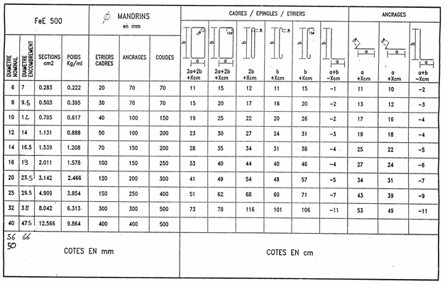
Several types of transverse steels exist:
Overlapping hoop: they confine the set of longitudinal bars (they are welded to them)
Hoop: they allow the flow of transverse forces inside the wall.
Stirrup: 2-piece bars connecting 2 groups of longitudinal bars opposite to each other
Cross tie: 1-strand bars connecting 2 groups of longitudinal bars opposite to each other
Additional length required to guarantee the loading lengths (depending on the diameter of the bar) :

