
Guide for using the new features
Guide for using the new featuresIntroduction« Pile » module« Water flow » Module« Sensitivity » moduleInternal stability of a nailed soil massif (NF P 94 270 – October 2020)Internal stability assistantSeismic moduleDetermination of seismic coefficients (Eurocode 8)Search for the most unfavourable combination of and Automatic search for destabilising seismic accelerationWizard for assessing irreversible post-earthquake displacementAutomatic calculation of the safety factor with the kinematic method of yield design calculationDetermination of the safety margin against external loads.
Introduction
This document aims to present the new features of the new version of Talren (v6).
This new version integrates a new calculation kernel, several new features as well as additional modules allowing to extend the application fields of the software.
The new features are :
- « Pile » module
- « Water flow » module
- « Sensitivity » module
- Internal stability of a nailed soil massif (NF P 94 270 – October 2020)
- Internal stability assistant
- Seismic module
- Automatic calculation of the safety factor with the kinematic method of yield design
- Determination of the safety margin with respect to external loads.
« Pile » module
This additional module allows a more accurate estimation of the resistance contribution along a reinforcement element of the "nail" type, representative of a pile, an inclusion or a barrette working in flexion-shear. The calculation is based on a "p-y" type elasto-plastic model taking into account the multi-layer nature of the soil.
Talren v6 allows the consideration of a multilayer soil around the pile and integrates the possibility to take into account the plasticization of the soil, which will lead to obtain a higher shear force compared to the calculation performed with Talren v5 where the working domain of the "nail" was limited to the beginning of the plastic domain of the soil.
In general, a pile will tend to plasticize after the soil, which allows full use of its bending-shear strength to determine a higher shear force than that found with Talren v5.
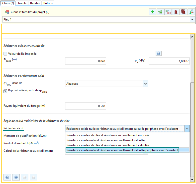
Required conditions
The search for the mobilisable shear diagram is performed in the calculation phase. To trigger this option, the axial calculation rule for each nail for which we want to start this search must be defined as follows:
Access to the module
Then access the phase where the nail to be processed is active, the new module is accessible via the following button:
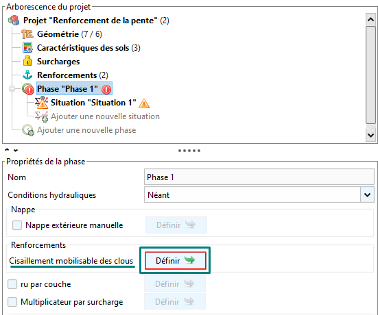
Use of the module for search the mobilizable shear of nails
The module is composed of 2 tabs:
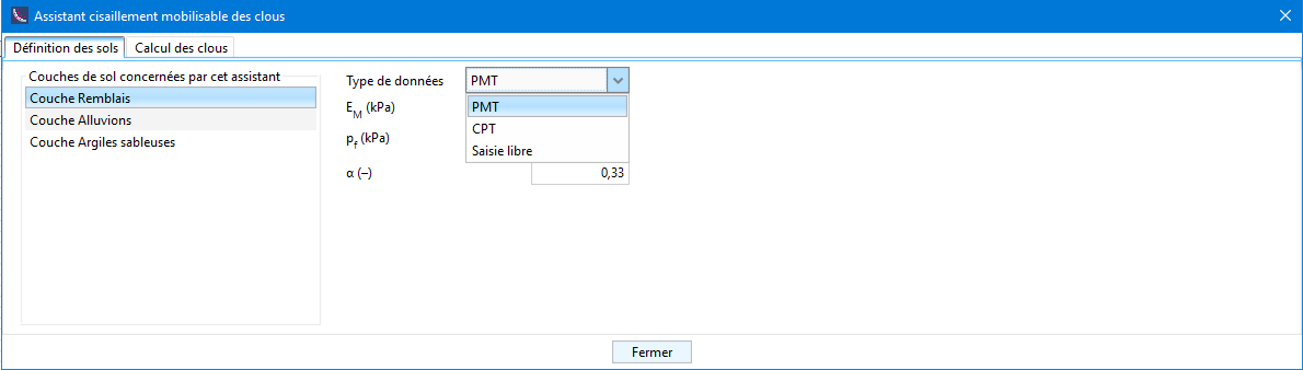
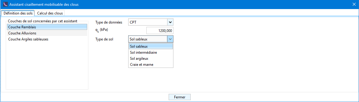
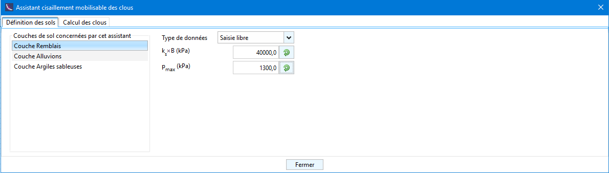
Tab Soil definition: it lists all the soil layers traversed by the active nails in the current phase that must be characterised to define the frontal reaction law, i.e. :
From the pressuremeter data (PMT), defining:
- : pressuremeter module [kPa]
- : creep pressure [kPa]
- : rheological coefficient [-]
From penetrometric data (CPT), defining:
- : cone resistance [kPa]
- Type of soil : soil category as defined by standard NF P 94-262
Customized input :
- : reaction modulus, i.e. the slope of the frontal reaction law [kPa]
- : maximum pressure that the soil can support [kPa]
Tab Nail calculation: allows the calculation of the mobilisable shear force diagram of each "nail"
The drop-down list allows you to choose the pile to be manipulated, the calculation parameters already defined at the beginning are displayed as a reminder:
- Equivalent diameter B [m]
- Product of inertia EI [kN.m²]
- Total length of the element [m]
- Plasticity moment, i.e. the bending moment that must not be exceeded [kNm]
- Length to be examined: External or Internal/External
A summary table of the stratigraphy traversed is then displayed, specifying the value of the surface stiffness of each soil layer ( [kPa/m]) as well as the maximum value of pressure that the soil is allowed to support. ( [kPa]).
In addition, there are several digital options available to us:
Possibility to take into account soil plasticization :
- If this option is checked, plasticisation will be allowed, the mobilisable shear will tend to be larger.
- If this option is unchecked, plasticization will not be allowed and the average soil pressure will be limited to the value of , which will allow to reproduce the results of Talren v5.
Possibility to take into account or not a possible plastification of the nail :
- If this option is checked, the generation of a plastic hinge is allowed in the nail for the cases where it will plasticize before the ground.
- If this option is unchecked, the calculation is stopped as soon as the bending moment obtained is equal to or greater than the plasticizing moment, without generation of a plastic hinge.
Maximum calculation step [m]: discretization of the nail which fixes the levels at which the search for mobilizable shear will be carried out.
Number of subdivisions [-]: number of sections that will make up the nail according to the maximum calculation step defined above.
Number of calculation points [-]: used to define the discretisation of each length (internal/external) to be treated for each level examined.
Number of loading increments [-]: number of times the initial loading will be applied to each examined level.
Maximum number of iterations [-]: number of times the iterative process will be allowed to try to converge to find the balance between the nail and the ground.
Relative tolerance [-]: calculation parameter which allows to decide on the convergence, by default equal to .
Initial load [kN]: initial force that will be applied to each level examined.
The lower buttons allow either to launch the calculation of the active nail (the one selected in the drop-down list), or to launch the calculation of all the active nails in the current phase (all those in the drop-down list).
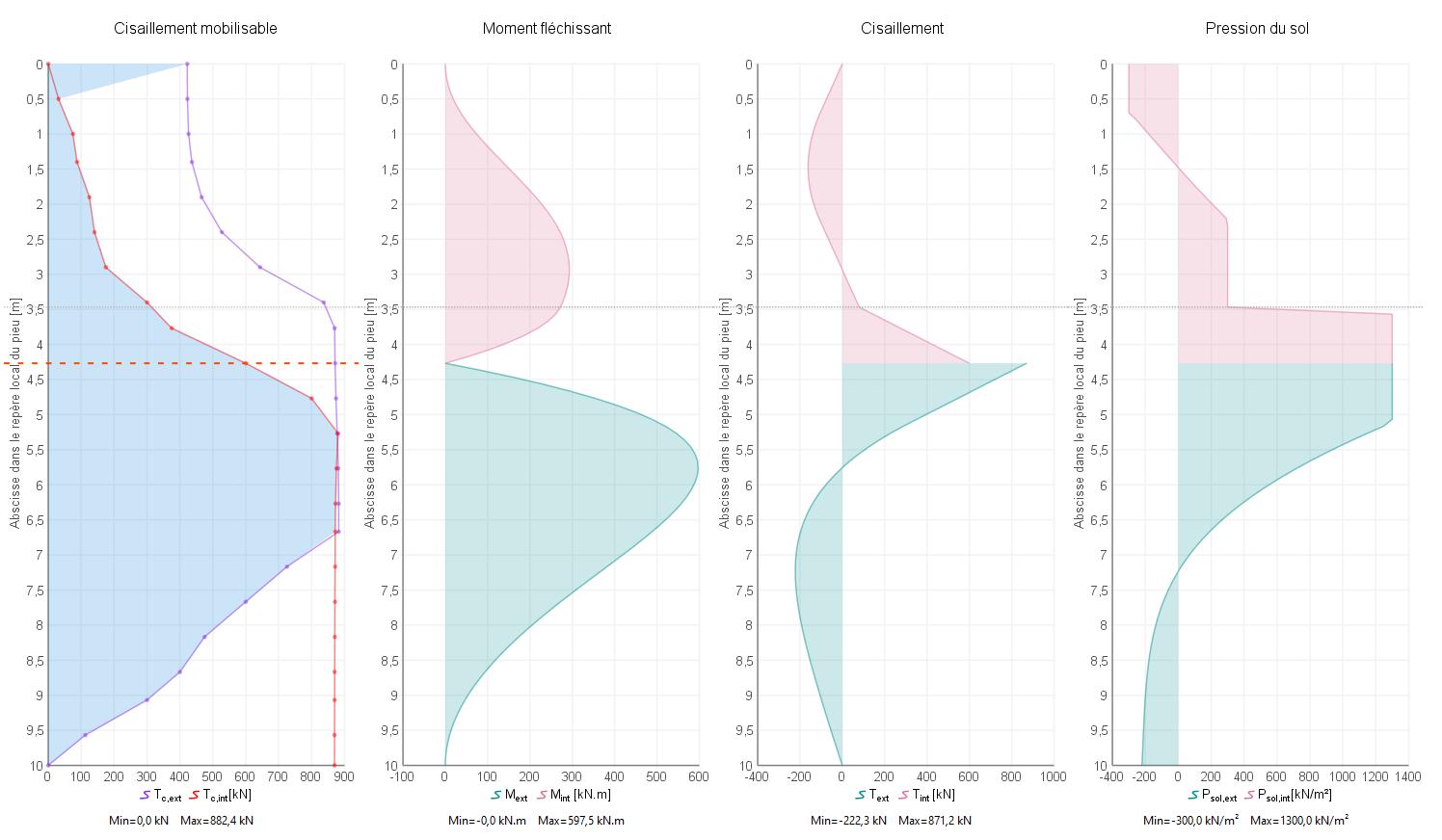
Once the calculation is launched, it is possible to click on each examined level of the Shear mobilisation graph to access the following diagrams for each length that has been examined (internal/external):
- Mobilizable shear [kN]
- Bending moment [kNm]
- Shear [kN]
- Soil pressure [kN/m²]
The obtained mobilisable shear diagram will be an input to the stability calculation performed by Talren v6 for all situations within the current phase.
As the soil around the nail can change from one phase to another, this should be done for all phases where each nail for which the mobilisable shear diagram is requested is active.
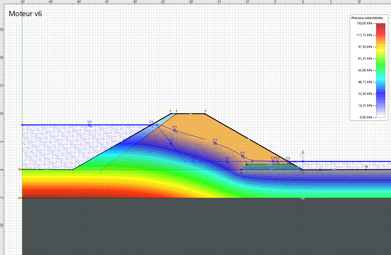
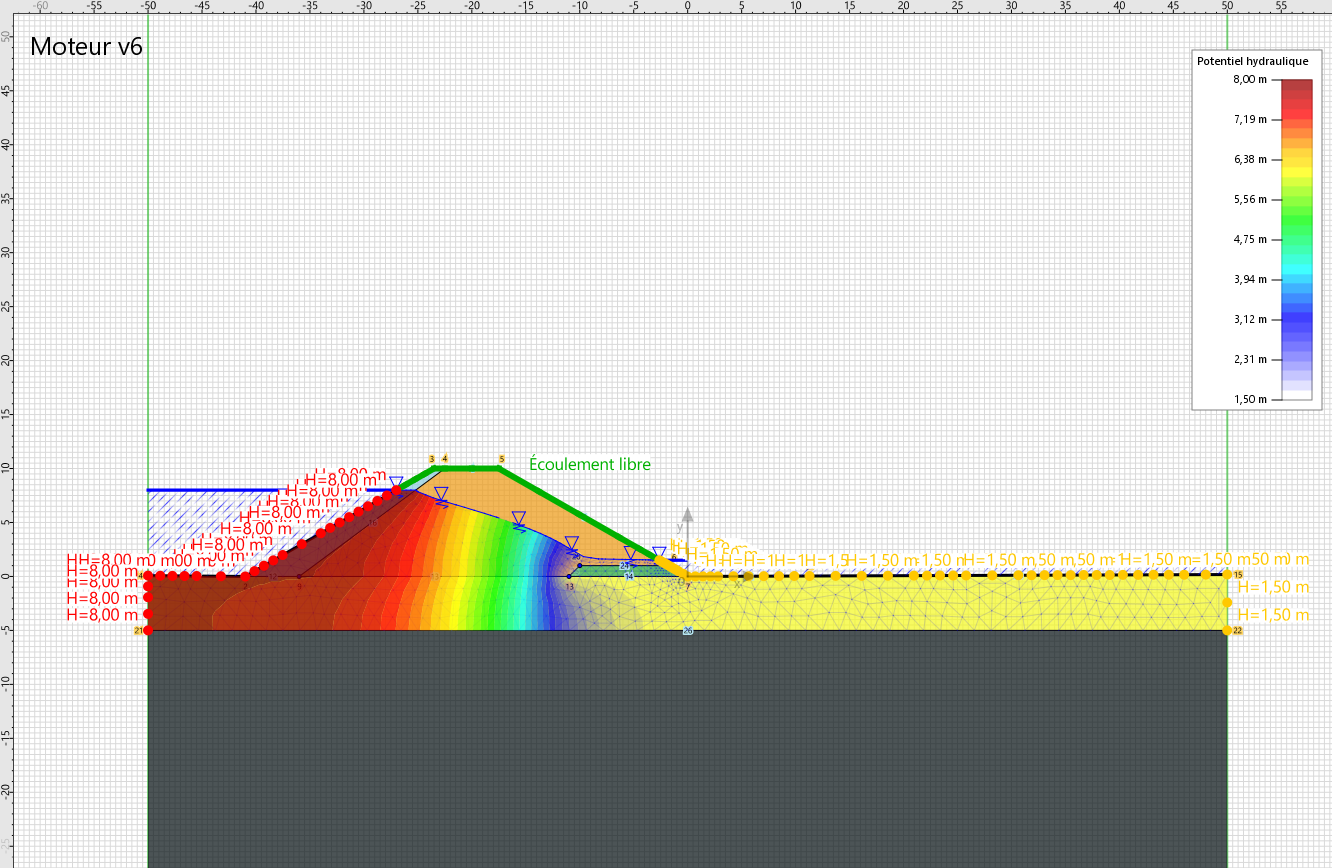
« Water flow » Module
This module allows an integrated calculation, under steady state conditions, of the pore pressure field to be considered for stability analyses. The calculation is based on a numerical resolution of the Laplace equation taking into account the multilayer and anisotropic character of the ground (vertical and horizontal permeabilities are differentiated).
This flow calculation is complementary, i.e. at the request of the user in each calculation phase. The old modes of hydraulic conditions remain unchanged compared to the previous version (water table, pressures given along a polygonal rupture surface and triangular mesh of pore pressures calculated).
The hydraulic conditions resulting from this additional module will constitute an input to the mechanical problem when assessing the stability of the structure. They will be used, in particular, to evaluate the effective stresses in the soil.
Talren v6 allows to choose in which soil layers the flow can develop and in which the flow is not allowed (i.e.: impermeable horizons).
This choice is made when defining each soil layer (by default, flow is not allowed in any new layer):
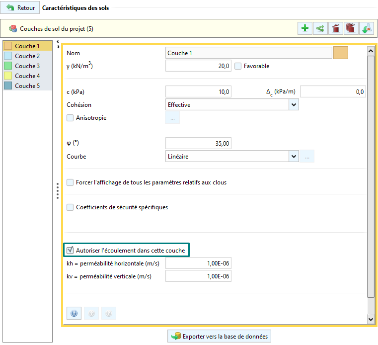
In soils where flow is allowed, it is necessary to define :
- : horizontal permeability [m/s]
- : vertical permeability [m/s]
If flow is not allowed in a soil layer, it will be considered impermeable.
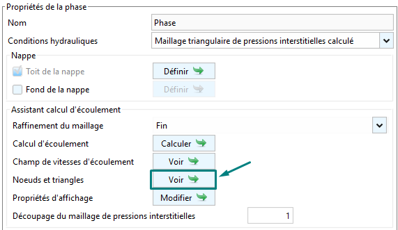
When defining the calculation phase, you should choose : Triangular pore pressure mesh calculated to be able to start the flow calculation:
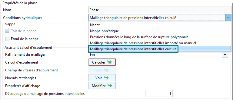
First of all, the boundary conditions must be defined. This is done by defining the Water table using the Define button:
Only the conditions at the ends of the model and at the level of the intersection with the natural ground will be "prescribed values". Talren then looks for the position of the water table within the ground.
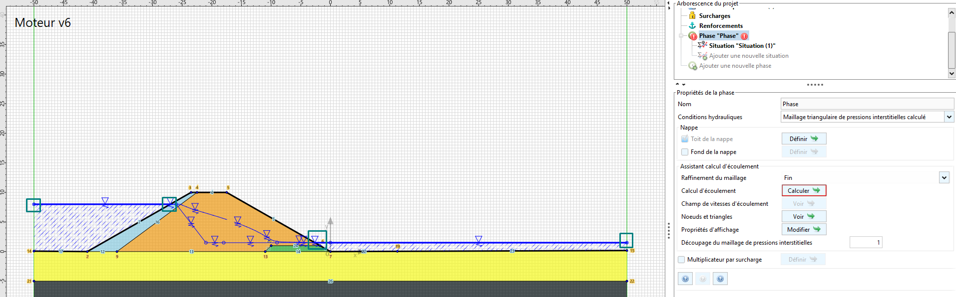
The flow calculation module allows you to choose the mesh refinement:
- Very coarse
- Coarse
- Medium
- Fine
- Very fine
In general, a refinement of type "fine" (default choice) is sufficient for common projects.
The flow calculation is started via the Calculate button.
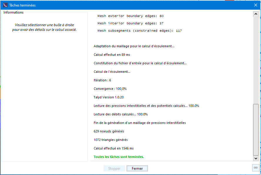
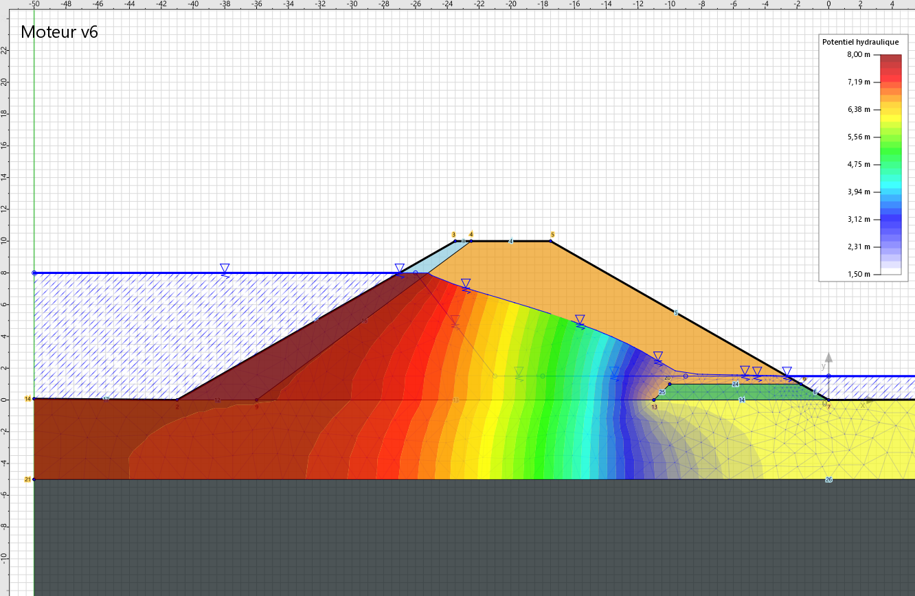
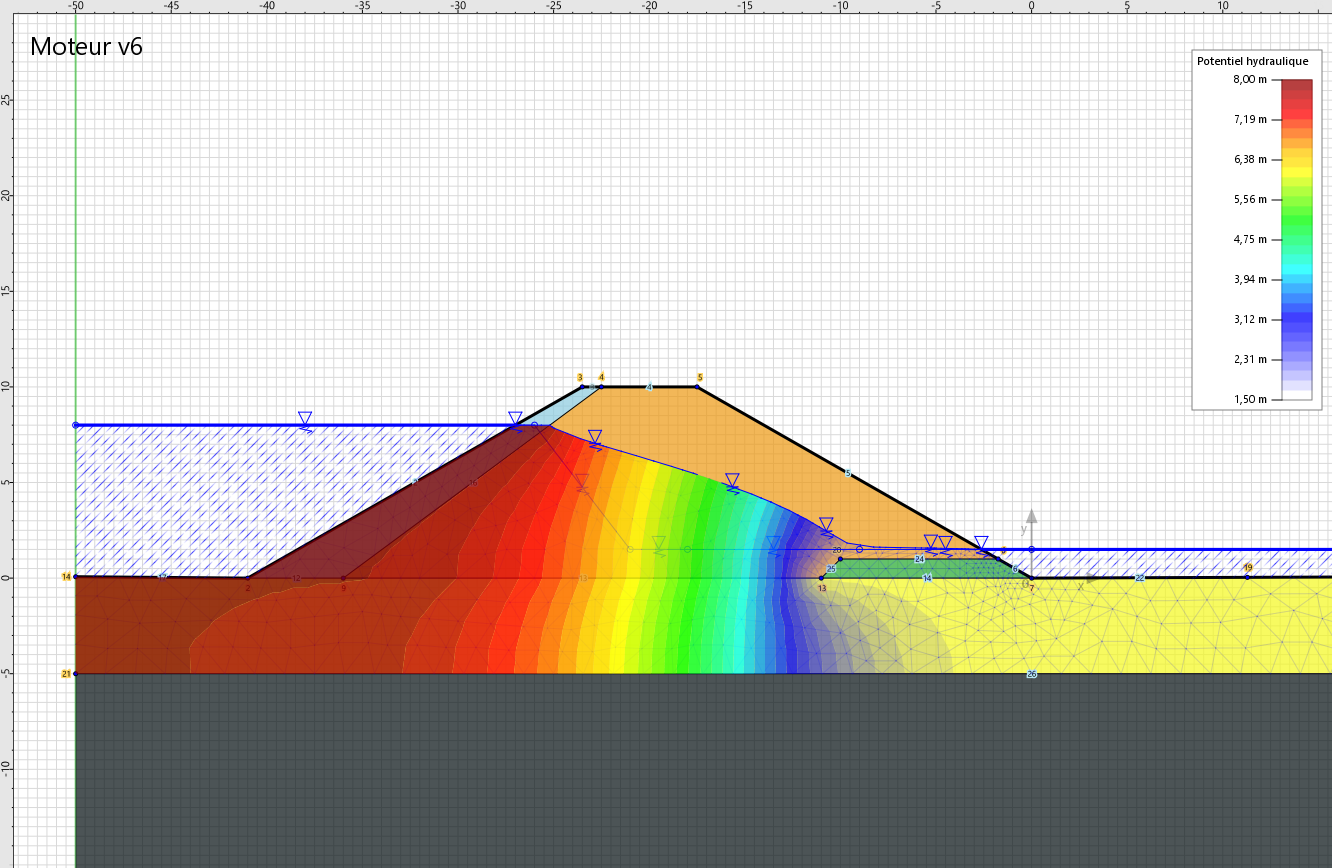
Once the calculation is complete, Talren displays the hydraulic potentials, which allows us to identify the equipotential lines:
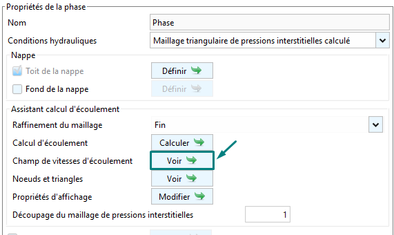
The flow velocity field can be viewed via the View button:
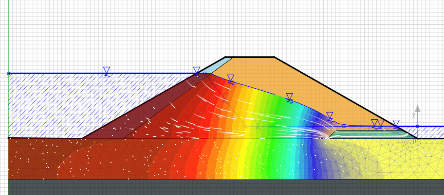
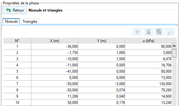
The coordinates of the nodes and triangles used in the calculation are accessible via the View button:
In the Display Properties menu, the following options are available:
Show isovalues: if checked, the results are coloured on the drawing area.
Soft continuous mode (slower) : if checked, a gradient is applied along the isovalues, which does not allow the equipotentials to be identified.
Magnitude to be represented :
- Hydraulic potential, or
- Pore pressure
- Display Boundary Conditions: this allows you to view the boundary conditions imposed during the flow calculation and which conditions the distribution of hydraulic potentials and pore pressures.
« Sensitivity » module
This module offers the possibility of automatically conducting sensitivity studies to evaluate the influence of the various model parameters on the stability of the structure studied. It is also possible to perform a reliability analysis, which consists in quantifying the safety in terms of reliability index or failure probability (analysis based on the RSM method).
The "Sensitivity" module is part of the properties of the situation and is accessible via the Define button:
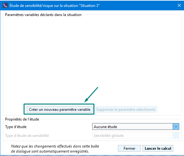
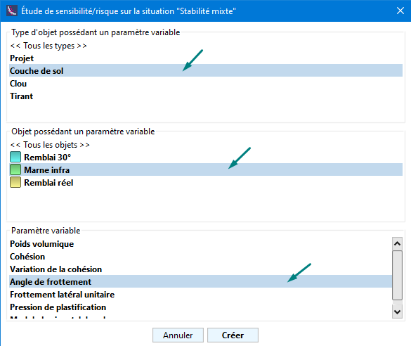
In order to launch the sensitivity study, it is necessary to create as many parameters as you wish to vary via the Create a new variable parameter button.
Each parameter to be varied must be selected beforehand from those already defined in the project and the active phase/situation.
The choice of parameter is made via the three lists of elements presented next. First, choose the type of object to be manipulated (Soil layer, for example), then the object to be manipulated (Marne infra, for example) and finally the parameter to be varied (Friction angle, for example).
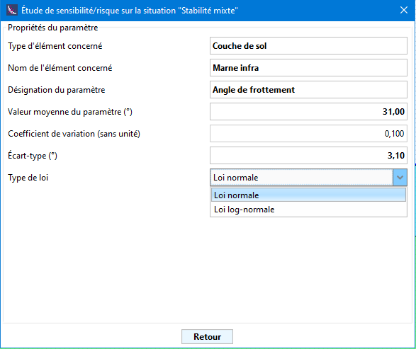
Next, it is necessary to define the variation of the parameter to be considered, in particular :
- The average value of the parameter [unit of the parameter]: the value proposed corresponds to the one entered during the definition of the project.
- Coefficient of variation [unit-less] to be considered, usually defined as the ratio between the standard deviation and the mean.
- Standard deviation [unit of parameter] to be considered, a measure of the dispersion of the sample values.
- Type of law: choice between normal law and log-normal law.
Once the variation of the parameter to be considered has been defined, all the information is displayed in the main window of the assistant:
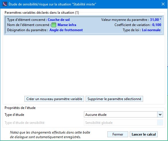
It is possible to define as many parameters to vary as desired:
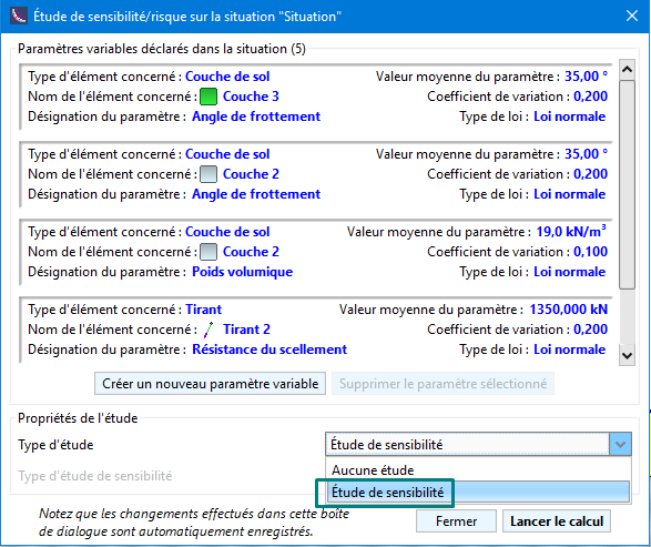
To initiate the sensitivity study, a Sensitivity Study study type must be selected. The No Study option allows you to keep track of changes in the defined parameters without initiating the sensitivity calculation.
It is possible to start the calculation immediately using the Start Calculation button. As soon as the window is closed, it is quite possible to launch the same calculation by calculating the situation.
Once the calculation is completed, Talren announces the relative sensitivities that have been calculated based on the possible variation of each parameter:
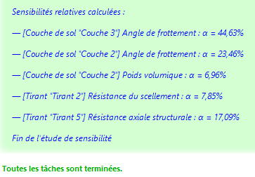
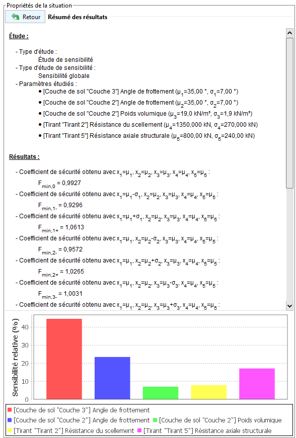
This study makes it possible to appreciate the influence of each parameter on the equilibrium calculation. The detailed results indicate the value of the stability coefficient (F) obtained for each value of the parameter examined while keeping the average value of the other parameters chosen, for example:
- : value of F obtained for a parameter value equal to
- : value of F obtained for a parameter value equal to
Internal stability of a nailed soil massif (NF P 94 270 – October 2020)
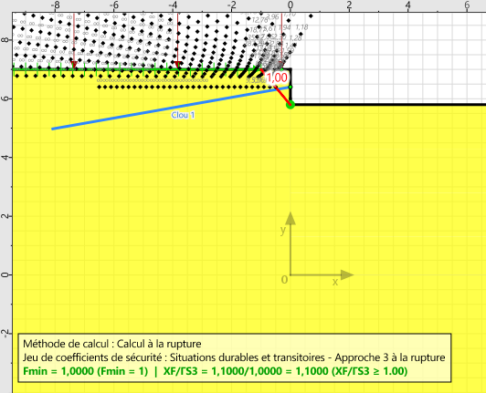
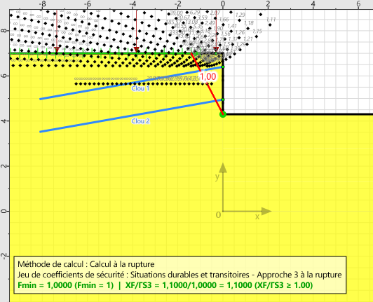
Talren v6 now offers the possibility to automatically specify and/or set the nail head forces required to verify the internal stability of a nailed soil mass, in accordance with the provisions of the new NF P 94 270 standard dated October 2020.
The principle of the modelling consists in foreseeing a phase (and a situation) for each stage of earthworks. In each situation, we will ask Talren v6 to find the force to be applied at the head of the nail that is placed at that moment (and that will have to be mobilised by the facing) so as to reach the limit equilibrium (), while keeping the forces at the head that were previously found in the rest of the nails already placed. It is also possible to consider a redistribution of the forces on all the active nails at each phase (and situation).
This approach to setting the forces at the head of the nails assumes the implicit contribution of the axial force that can be mobilised over the internal length of the nail (that contained in the sliding soil block).
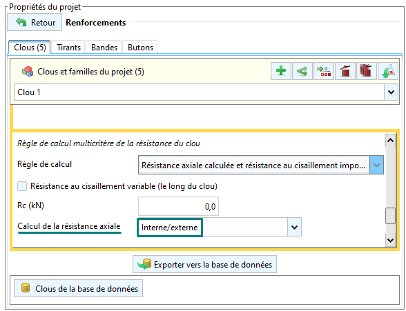
It is therefore necessary to allow the calculation of the axial resistance on the Internal/external length when defining each nail to be handled in this setting approach.
It then becomes necessary to decide on the way in which the nails are placed on site. It is usual to consider the excavation of the passes by studs, which allows the nails to be placed alternately on the same bed. In the calculation, this makes it possible to excavate a new pass by considering the presence of the bed of nails present near the level of excavation of the pass.
In all cases, the phasing must include a calculation phase for each earthwork and nail bed placement pass.
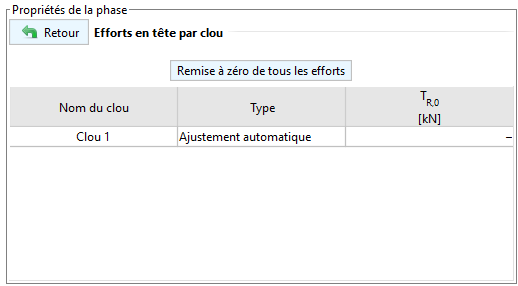
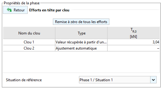
The calculation of the forces at the head of each bed of nails is done at the level of the situation of each phase (the Define button is accessible once the box is checked):
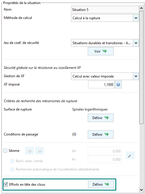
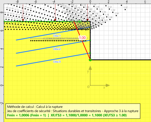
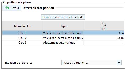
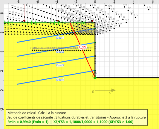
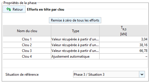
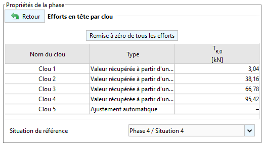
Below is the classic setting that is recommended for each phase/situation: the head force of the last bed of nails is requested to be automatically adjusted while keeping the head forces of the other beds of nails that have already been installed (). To do this, it is necessary to define a reference phase/situation common to all the nails for which the nail head force is to be recovered. If desired, it is also possible to enter the value of the head force (manual entry).
The automatic adjustment initiates the search for the nail head force that needs to be mobilised to reach the limit balance.
| Phase 1 | Setting Situation 1 |
|---|---|
 |  |
| Phase 2 | Setting Situation 2 |
 |  |
| Phase 3 | Setting Situation 3 |
 |  |
| Phase 4 | Setting Situation 4 |
 |  |
| Phase 5 | Setting Situation 5 |
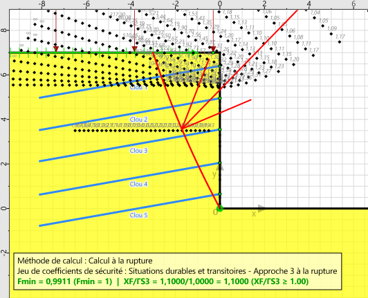 |  |
It is also possible to request the redistribution of efforts over several nail beds at the same time. To do this, it is sufficient to request automatic adjustment on several active nail beds within the same phase/situation.
At the end of the calculation of the situation, the effort mobilised at the head associated with the limit equilibrium is provided in the results:
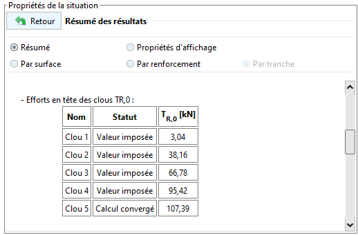
Meaning of the calculation status :
- Prescribed value: a value has been given by the user
- Not applicable: > 1 without mobilisation of the forces at the head of the nails (the manually entered forces are however taken into account)
- Converged calculation: the search for the head effort for which = 1 has been successfully completed
- Internal stability problem: the value of = 1 cannot be reached and the increase in the force at the head no longer allows to be increased.
- External instability failure: failure in the nails occurs in the steel or by friction on the external length
- Divergent calculation: no surface was generated, problem with the calculation of nails (wrong definition or missing information)
Internal stability assistant
Talren v6 also offers the possibility to calculate the forces in the reinforced concrete facing of a nailed wall (stress and bending moments).
The internal stability assistant is accessible from the results window of any situation where there are active nails: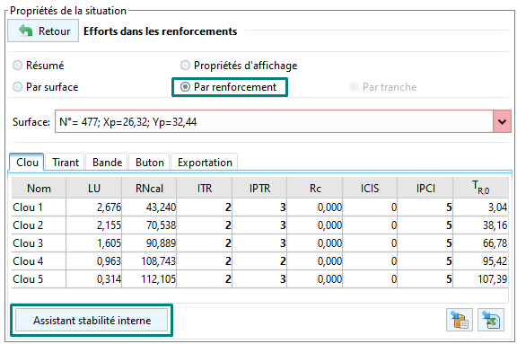
The wizard allows you to choose the nails and situations (among those calculated) to be considered for calculating the forces in the facing:
The Ctrl key is used to select multiple nails or phases/situations.
The Shift key is used to select several nails or phases/situations at the same time.
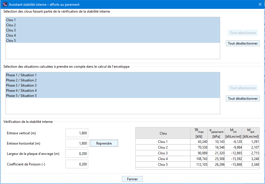
The calculation of the forces in the facing requires the following parameters to be entered:
Vertical spacing [m] : average vertical spacing of nail beds
Horizontal spacing [m] : horizontal spacing of nail beds
The Resume button is used to recover the value entered when defining the nails.
Anchor plate width [m]: value to be entered (default is 0.20 m).
Poisson's ratio [-]: value to be entered (default is 0.20).
As the previous parameters are selected and entered, the table at the bottom right is updated to retain the effort "seen" by each nail over the set of selected phases/situations. The calculated results are as follows:
| Result | Unit | Description |
|---|---|---|
| kPa | Average stress at the wall | |
| kNm/m | Bending moment tensioning the inside fibre of the wall | |
| kNm/m | Bending moment tensioning the outer fibre of the wall |
Seismic module
Talren v6 offers several new features related to seismic aspects:
Determination of seismic coefficients according to Eurocode 8.
Automatic search for the destabilising seismic acceleration (that leading to the limit equilibrium)
This destabilising seismic acceleration can be used as an input to assess the irreversible displacement using the wizard below.
Assistant to assess the irreversible post-earthquake displacement :
- Empirical approaches: Ambraseys and Menu (1988), Jibson (2007) and Lazari and Padopoulos (2012)
- Quantitative earthquake approach using the Newmark method
Determination of seismic coefficients (Eurocode 8)
Seismic conditions are defined at situation level.
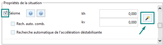
A new wizard is available in this new version to define the horizontal and vertical earthquake acceleration ratios according to Eurocode 8.
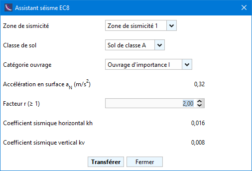
The parameters to be defined are the following:
Seismicity zone: zones 1 to 5
Soil class: classes A to E
Category of importance of the structure: from I to IV
The surface acceleration [m/s²] is then determined according to the previous parameters.
Factor r (>=1): this coefficient, taken from EC8, is intended to reflect the capacity of the structure to move or not under seismic action. The choice of an "r" greater than 1 is favourable to the design and therefore consists of designing with a seismic acceleration equal to a fraction 1/r = 0.5 to 1 of the maximum acceleration, which means that a displacement (which can range from a few mm to a few cm) of the structure studied is implicitly authorised. This displacement is only possible if the structure is "isolated" (e.g. a maritime quay, a heavy retaining wall, etc.)
The horizontal () and vertical () seismic coefficients are then deduced and can be transferred to the situation.
Search for the most unfavourable combination of and
Talren v6 allows to get rid of the sign of definition of the seismic coefficients. It is possible to ask it to examine the 2 possibilities: lightening earthquake and weighing earthquake combined with a horizontal acceleration towards the right. In this case, the values of and must be entered as absolute values.
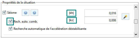
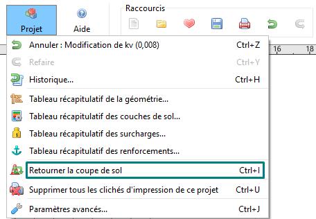
We remind you that Talren v6 only examines kinematics to the right. If the project has been defined in "reverse", it is quite possible to reverse it using the Ctrl+I key or from the Project - Reverse Ground Section menu.
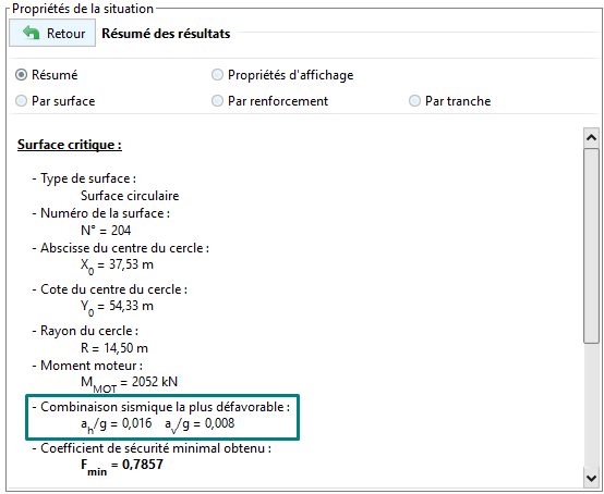
After calculation, the most unfavourable seismic combination is found:
Automatic search for destabilising seismic acceleration
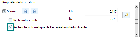
Talren v6 offers the possibility to automatically search for the destabilising seismic acceleration (the one leading to the limit equilibrium). This acceleration is searched as a multiple of the acceleration.
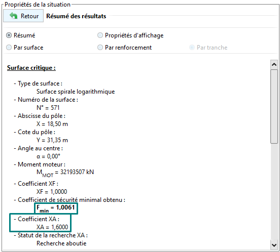
Once the calculation has been completed, Talren provides the multiplication coefficient XA that has been applied to the values of and to arrive at the limit equilibrium (=1.00).
Wizard for assessing irreversible post-earthquake displacement
Talren v6 also includes a wizard for assessing irreversible displacement outside of any project.
It proposes two approaches:
Empirical approaches:
Ambraseys and Menu (1988) 
Jibson (2007) 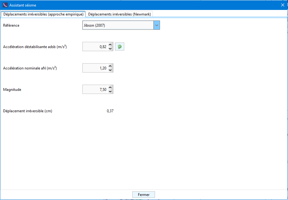
Lazari and Padopoulos (2012) 
Quantitative approach (Newmark): this wizard completes the pseudo-static calculations made by Talren from the seismic coefficients and .
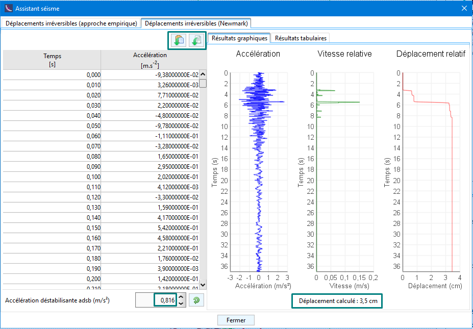
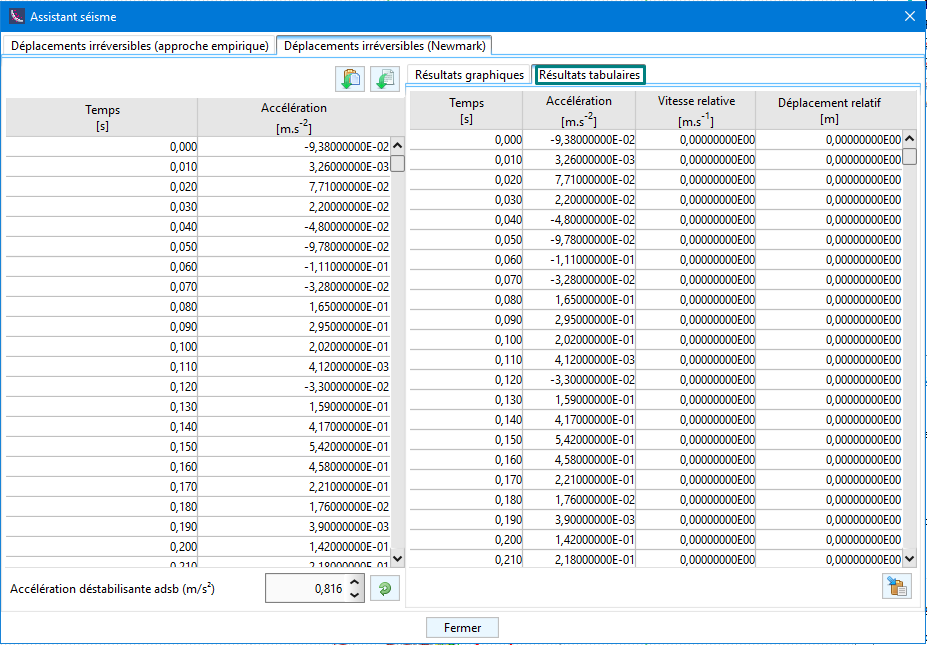
The wizard requires as input :
- The accelerogram which can be imported directly from the clipboard (for example, by copying and pasting it into Excel beforehand) or from a .txt file using the buttons available on the left-hand side of the table
- The disturbing acceleration [m/s²] which can be entered manually or retrieved using the button on its right.
The accelerogram is then plotted and integrated to obtain the velocity to obtain the cumulative relative displacement which is plotted on the right.
The results are also displayed in tabular form:
Automatic calculation of the safety factor with the kinematic method of yield design calculation
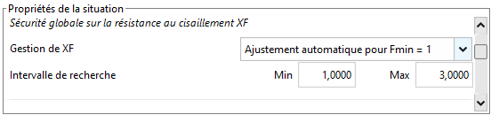
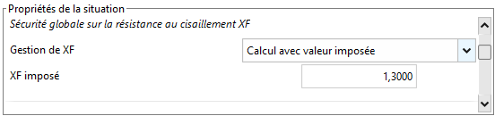
This new version also makes it easier to use the kinematic method of calculation at failure with the possibility of automatically setting the XF factor (which plays the role of the safety factor with regard to the shear strength).
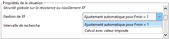
This option is available when defining the situation with two possible choices:
Automatic adjustment for : it is necessary to limit the range of values of XF that one wishes to examine.
By default, the range examined is =1.00 to =3.00, but this can be extended as required.
Imposed value calculation: This calculation reproduces the calculation of the previous version by prescribing a specific security level.
Determination of the safety margin against external loads.
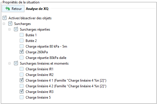
It is now also possible to specifically identify safety margins for external overloads applied in the field (new XQ factor).
This option is available in the situation definition:
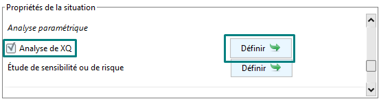
The XQ analysis consists of evaluating the possible increment that can be applied on the selected surcharges to reach the limit equilibrium (=1.00). The surcharge will be the same on all selected surcharges.
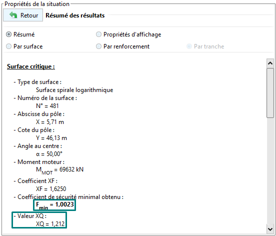
After calculation, the XQ coefficient is found in the results of the situation under review.
![]()